
Important updates:
- Due to erratum 84 (COMP: ISOURCE not functional), capacitive sensing using the relaxation oscillator method is not usable in a real product with the nRF52832, as it will only work reliably in room temperature. The ISOURCE feature is not present in the nRF52840 nor nRF52810.
- After this tutorial was written, SDK 12 was released with support for capacitive touch using the Capacitive Sensor driver and Capacitive Sensor library.
Introduction
Scope
The following topics will be covered in a varying degree of detail:
- Use cases for capacitive sensing.
- Basic principles of capacitive sensing.
- A simple example of capacitive buttons on the nRF52.
The details of analyzing capacitive sensors is out of scope of this tutorial. As is advanced processing of the sensor data. The accompanying example is simple, but is provided as a proof of concept and a possible starting point for further development.
Required prior knowledge
It is expected that you are familiar with the basics of embedded C programming. You should also have basic knowledge of how to build and download firmware to the nRF52 DK. Refer to Getting Started in the SDK documentation if this is unfamiliar territory. Moreover, the example use a few nordic libraries that will not be explained in detail. Refer to the SDK documentation for details on those.
Required equipment and software
Hardware:
- nRF52 DK.
- Capacitive sensor of some sort (a piece of copper tape will do).
Software:
- GCC ARM Embedded or Keil 5.
- nrfjprog or nRFgo Studio.
Other files:
- Example project: nrf52-capsense-example.
Use cases for capacitive sense on the nRF52
Capacitive sensors have no moving parts and are normally protected by a surface material, such as glass or plastic. This makes capacitive sensors more reliable than mechanical sensors, and a better choice for products that are exposed to the environment or need regular cleaning. The sensor can be made in any shape, and need not be on a flat surface. Moreover, with the built in support in the nRF52, capacitive sensors are very low cost, as no external components are required.
The sensor can be made to have a application range, from fractions of a millimeter up to several centimeters. Depending on the sensor it can be used to make precise buttons, or it can be used to detect if a device is held in a hand or not.
The following is a list of possible use cases for capacitive sensing with the nRF52:
- Buttons
- Sliders
- Rotation sliders
- Detect if held by hand or not
Principles of capacitive sensing
Capacitive sensing is based on capacitive coupling and utilizes the body capacitance. Refering to the parallel-plate model of a capacitor, the sensor electrode (usually copper on the PCB)) can be seen as a plate of a capacitor, where for example air, glass or plastic is the dielectric and the finger acts as the other plate.
The capacitance, C = (εA)/d, where ε is the permittivity of the dielectric material between the plates, A is the area of the plates, and d is the distance between the plates. A large object such as a hand will result in a higher capacitance than a small object such as a finger. Moreover, a close object will result in a higher capacitance than a remote object. This means a close finger may result in the same capacitance as a more remote hand, making the two cases indistinguishable.
Changes in capacitance can be monitored in order to detect changes in the environment, such as a finger closing in on a button. In a nutshell, the higher capacitance, the "harder" the press.
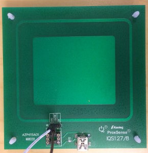
The design of a sensor depends on the use case. As the size of the sensor electrode determines the sensitivity of the sensor, a generic proximity sensing sensor would normally have a large surface, as shown in the picture.
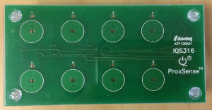
Button type sensors will normally be smaller, as is the case with this 8 button keypad.
Simple sliders or rotation sliders can be made from separate buttons in close proximity. However, using more complex sensor shapes make it possible to get higher resolution using fewer pins. With a sensor configuration similar to that shown below, the finger will always interact with two sensors simultaneously, and the location of the finger on the slider can be quite accurately calculated. For a slider this would require at least two electrodes, and for a rotation switch a minimum of three electrodes must be used. The sketch below shows a slider with 4 electrodes.

The capacitive sensor electrode is often just copper on the PCB.
There are several methods that can be used to detect changes in capacitance. This tutorial will only mention two, which use different methods of detecting the changes in capacitace based on changes in the rise and fall time (given by the RC time constant):
- Resistor capacitor (RC) charge timing.
- Relaxation oscillator (RO).
RC charge timing
Using RC charge timing, the change in capacitance is found by measuring the charging or discharging time of the sensor capacitor via a resistor. Thus it requires one external component, a resistor. Two pins are required per button:
- one GPIO output pin for charging the sensor capacitor via a large resistor (e.g. 1–10 MΩ).
- one analog input pin connected to the sensor electrode at the same point as the GPIO (without the resistor). This is used to measure the voltage over the sensor capacitor.
The measuring device (e.g. a nRF5x) will measure the time it takes to charge the sensor capacitor via the series resistor. This measurement can be considered a sample, and sampling will be performed at regular intervals.
The nrf51-capsense-example is a example of this method. It uses two pins and relies on the low power comparator (LPCOMP) and timer (TIMER) peripherals. The example is also valid on the nRF52 with minor modifications.
Relaxation oscillator
The relaxation oscillator method builds an oscillator which uses the sensor capacitor as a timing element. The frequency of the oscillator will dependent on the rise and fall time of the sensor capacitance. As the capacitance increases when an object is close to the sensor, the time constant will be larger and the frequency lower.

The comparator (COMP) module in the nRF52 includes hardware support for capacitive sensing. It can be configured to enable a current source that outputs a current on the selected analog pin, and create a feedback path around the comparator, forming a relaxation oscillator. A timer can be used to measure the period of the oscillator. These measurements can be done in hardware, by connecting comparator events to timer tasks using Programmable Peripheral Interconnect (PPI).
Calibration and post processing of samples
Both the methods described above will result in samples that in one way or the other is related to the capacitance of the sensor capacitor. These raw samples need processing, and cannot be used directly to indicate button presses. Both calibration and debouncing is needed.
Calibration of capacitive sensors is not straightforward. The sensor capacitance will change significantly not only due to the presence of objects (such as a human finger), but also due to changes in humidity, overlay materials (e.g. screen protector) etc. There can also be significant differences depending on how the device is used, such as if it is held in a hand or lying on a desk. Moreover, the nRF52 peripherals will perform differently at different temperatures, supply voltages etc. A proper calibration mechanism must be able to properly handle these changes in the environment seamlessly, while not mistaking a long touch as a change in the environment.
Example: Capacitive button sensing on the nRF52
This example will demonstrate how the Comparator peripheral (COMP) in the nRF52 can be used to implement capacitive buttons using only 1 pin per sensor and no external components. Two capacitive buttons are used; each will toggle a LED. The LED will glow when the button is "pressed". Though the nRF52 can also be used with complex sliders, as described previously in this tutorial, the example code can only handle simple buttons.
Hardware
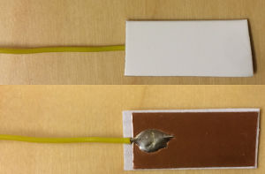
The example requires a nRF52 DK and some form of capacitive sensor. The capacitive sensor can be very simple, typically just a conductive surface. Virtually any form of capacitive sensor can be used. The following sensor is more than adequate, and can be made in less than five minutes:
- Cut a piece of cardboard to whatever size and shape you want for your button.
- Put copper tape on one surface.
- Solder a wire on the copper surface.
The sensor can look something like this:
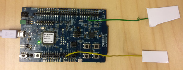
Connect the sensor to one of the 8 analog input pins on the nRF52 DK. The mapping between the analog input numbers and GPIO port numbers (printed on the PCB silkscreen) can be found in the Pin assignments section in the Objective Product Specification.
The rest of the example will assume that two sensors are used, and that they are connected to analog input 2 and 3, marked as P0.04 and P0.05 on the PCB of the nRF52 DK. They each represent a button. The setup is shown below.
Software
The nrf52-capsense-example example project has a simple capasitive sense driver and example. The example in its current state is intended as a proof of concept, and is not suitable for end products.
The example is based on nRF5 SDK 11. It is intended for the zipped version of the SDK and will not work with the Pack installer.
To get started, clone the nrf52-capsense-example repository to <SDK>\examples\peripheral. The project comes with a Makefile for GCC (pca10040\blank\armgcc\Makefile) and a project for Keil 5 (pca10040\blank\arm5_no_packs\nrf52_capsense_example_blank_pca10040.uvprojx).
The project uses the following hardware resources on the nRF52:
- The comparator.
- One of the timers (TIMER1 by default).
- 2 PPI channels.
- A real time counter (RTC1, using the application timer library).
Most parameters of the driver are configured by modifying the defines in nrf_capsense_cfg.h. This include number of buttons, calibration, debouncing and allocation of timer and PPI channel resources. The nrf_capsense_init() function is used to initialize the driver by supplying a pointer to a static configuration struct. This struct, nrf_capsense_cfg_t, holds a function pointer to the application's event handler (callback function) and the sensor pin numbers.
The example measures the time of a half period of the signal generated by the relaxation oscillator, which frequency depend on the sensor capacitance. Sampling is initiated by software, but the complete sampling sequence is performed in hardware using PPI. Once a sample is collected it is post-processed in software, applying calibration and debouncing.
A raw sample is generated in the following way:
- Sampling is initiated by setting the pin select register in the comparator to the pin of the button to be sampled. then starting the comparator. This effectively starts the oscillator.
- The first upward crossing of the comparator starts the timer via PPI.
- The downwards crossing of the comparator causes the timer to capture the timer value and stops the timer (again via PPI). It also triggers a comparator interrupt.
- The comparator interrupt handler reads the raw sample value, which is stored in the timers capture register. This is the time between a upward crossing and a downward crossing, which is effectively the time of a half period.
Before the buttons can be used, they must be calibrated. In this simple example, calibration data is only collected at startup by calling nrf_capsense_calibrate(). This must be done after the call to nrf_capsense_init() and before any calls to nrf_capsense_sample(). Those calibration data never change. Note that this is based on the naive assumption that buttons are never pressed when calibration is run and, even more important, that the environment never changes. This assumption may hold at a engineers desk, but will not hold in a end product that is used in a variety of ways in a variety or changing environments. The calibration process is done by simply collecting a number of raw samples, storing the min and max value, and using (min + max) / 2 as the base line.
During normal operation, raw samples are collected as described previously. Then each raw sample is compared with calibration data, and a decision is made. If a sample is higher than the baseline + calibration margin, it is decided that the button is likely being pressed. At this point, the raw data is similar to that of a physical push button, and the remaining step is debouncing. The debouncing requires several processed samples to have the same value. If the state of a button has changed after debouncing, the callback function is called, informing the application.
The example application calls nrf_capsense_sample() every 10 milliseconds. When a change in a button is detected, the LED's are updated.
Building and running the example
If the example is extracted to a valid location in the SDK (e.g. examples/periperal), it should build without the need of any modification. Make sure that sensors are connected to analog input pin 2 and 3, or modify the pin numbers in the init_capsense() function in main.c accordingly.
The example use the UART/RTT logging library. By default the project is configured to log via RTT, as NRF_LOG_USES_RTT=1 is defined in the Makefile and Keil project. Open the SEGGER J-Link RTT Viewer and connect to the onboard debugger in order to view the log messages.
Once sensors are connected and application flashed, touching a sensor will cause the corresponding LED to light up. Moreover, the button mask is logged at every change.
Visualisation of the relaxation oscillator frequency
The frequency of the RO can be visualized by connecting the comparator to a GPIO output using PPI and GPIOTE. Note that the example disabled the comparator peripheral between samples, so you would not see a continuous signal unless the example is modified to use a single sensor and to leave the comparator peripheral always running.
In order to output the RO signal, configure a GPIOTE output to toggle on task out events, and connect the GPIOTE TASKS_OUT endpoint to the comparator EVENTS_CROSS. By connecting the GPIO to an oscilloscope one can easily see the effects of manipulating the sensor capacitance by e.g. moving a hand over the sensor.
Further improvements
Particularly the calibration method need more work before the example can be used in an end product. The calibration algorithm must seamlessly handle changes in the environment, as briefly outlined earlier in this tutorial.
In order to obtain a better compromise between power consumption and user experience it makes sense to use a slow sampling rate when the user is not interacting with the device. Once user interaction has been detected, the sampling rate could be increased and held high until a certain time after the last button press.
Top Comments
-

JoakimWSI
-
Cancel
-
Vote Up
0
Vote Down
-
-
More
-
Cancel
Comment-

JoakimWSI
-
Cancel
-
Vote Up
0
Vote Down
-
-
More
-
Cancel
Children