Last updated on 02/25/2021, see changelog at the end for more details
This guide is written for those who are working on the nRF9160 and are starting their firmware design soon or for those who have already started. I have collected some tips from my experiences with working with customers over the past couple years on their designs. Prior to going through this blog, I would recommend going through the nRF Connect SDK Tutorial to gain better familiarity with nRF Connect SDK (NCS). Other blogs/guides will be referenced below where appropriate.
Contents:
Support for Trace Collection
This is critical to be able to debug any network related issues that may occur during firmware development. It provides insight to the Nordic support team on the underlying communication that is occurring in the modem between the UE and eNB. Having the ability to collect traces on your custom board is rather simple but should be planned for in advance as it requires an extra UART. When designing your prototype board, it is important that you have this UART available where this trace data can be outputted. You can then use a UART to USB cable to connect to the Trace Collector application to collect the logs.
The Trace Collector Guide reviews how to enable this support in firmware. This is done by adding CONFIG_NRF_MODEM_LIB_TRACE_ENABLED=y to your prj.conf file and activating modem trace in your application (AT%XMODEMTRACE=1,2). By default, the nrf_modem library uses UARTE1 for outputting the trace data, though this can be configured to another UART peripheral if desired. To do this, you will need to modify the UARTE instance in the nrf_modem_os.c file here. The pins that are used for TX and RX are defined here.
Once you have collected a trace using the Trace Collector tool, you can open a DevZone ticket and attach the trace. Please also include the modem firmware version (AT+CGMR) in the ticket as that will be used to decrypt the trace.
LwM2M Carrier Library Integration
The LwM2M carrier library can be used in your application to connect to the operator network. It may be required for carrier certification, so it is best to integrate this early on if you know you will need it. The carrier library is delivered as a binary and can be found in nrf/lib/bin/lwm2m_carrier/lib/cortex-m33/hard-float. Releases of this library usually coincide with tagged releases of NCS. Documentation for the library can be found here.
Refer to the Application integration section of the documentation to get more information on how to integrate this into your own application. The nRF9160: LwM2M carrier sample is a standalone example that demonstrates this. The nRF9160: Asset Tracker application is a full-fledged application capable of connecting to the operator network. This can be enabled in Asset Tracker following the steps here to use the correct overlay when building.
I would recommend reading the full documentation page for the LwM2M carrier library as many questions can be answered there including TLS/DTLS requirements, security tags and keys, and carrier certification.
Low Power Modes (PSM)
Having your device go into PSM is one of the key benefits and features of the nRF9160. With 2.7uA sleep current (check out PCN134), you have the ability to really optimize for battery powered applications and conceive use cases that were previously not possible with cellular. We have also recently released an online power profiler for the nRF9160 found here. A user guide for this power profiler can also be found on the right side of that page. I would recommend to also check out the blog here on how to measure PSM sleep current.
Understand the requirements from your carrier about what PSM intervals are supported. For example, using a Verizon SIM card, you will be granted PSM TAU intervals of at least 190 minutes. A quick way to test this is to run the following commands in the AT Client sample.
AT+CEREG=5
AT+CFUN=1
AT+CPSMS=1,"","","00100100","00100001"
Here we have asked the network for 4 hours Periodic-TAU and 1 minute Active-Time.
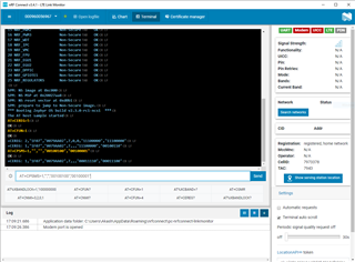
The screenshot below shows the commands being entered and the notifications from the modem. In this instance, we received +CEREG: 1,"1F07","0079AA02",7,,,"00011110","00011100" as the response from the network. 1F07 is the Tracking Area Code (TAC), 0079AA02 is the cell ID, 7 indicates LTE Cat-M1, 00011110 corresponds to 2 seconds * 30 = 60 seconds Active-Time, and 00011100 corresponds to 10 minutes * 28 = 280 minutes Periodic-TAU. Note that the order of the Active-Time and Periodic-TAU in the CEREG notification is reversed from the order in the CPSMS command. I would recommend testing varying Periodic-TAU to see what the network is giving you. You may get different responses based on the time that you request and the network load.
More information about these AT Commands can be found in the reference guide here.
Changelog:
02/25/2021
- Updated links for NCS v1.5.0
- Updated references from BSD library to nrf_modem library (this was introduced in NCS v1.5.0)
- Updated link for latest AT command reference guide
07/10/2020
- Initial release

