

This blog post provides step-by-step instruction on running Door Lock example from the CHIP repository. It demonstrates how with help of the mobile phone, commission accessory to the network using Bluetooth LE, and remotely control a door lock device with one basic bolt over Thread.![]()
Figure 1. Door Lock example - demo setup.
Table of Contents
- Introduction to Project Connected Home over IP (CHIP)
- Setting up a demo
- Conclusion
Introduction to Project Connected Home over IP (CHIP)
The primary goal of the Connected Home over IP project is to simplify development for manufacturers and create a plug-and-play experience for customers by increasing interoperability among smart home devices.
CHIP technology is based on IP and IP bearing transport protocols such as Wi-Fi or Thread. It also leverages the fact of the vast availability of Bluetooth devices (in our phones or tablets) and uses Bluetooth Low Energy to commission and provision accessories into the CHIP network.
Specification and implementation take advantage of development work from existing ecosystems that are currently competing with one another. This includes key technologies from Amazon’s Alexa Smart Home, Google’s Weave, Apple’s HomeKit and the Zigbee Alliance’s Dotdot specification.
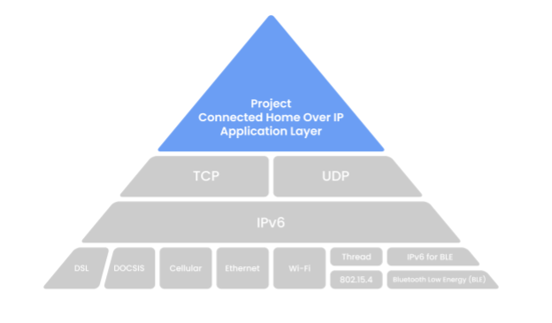
Figure 2. Connected Home over IP - an architectural overview.
The specification and implementation of Project Connect Home over IP are under development and Zigbee Alliance continues to drive towards releasing the standard in 2021.
Project Connected Home over IP is developed in the open and transparent way as a GitHub repository under Apache v2 license.
This tutorial gives insight on the early implementation of the CHIP protocol. Please note that neither of the showcasing operations presents the complete and final way of interaction.
Setting up a demo
This section shows how to set up, commission and control CHIP-based Door Lock accessory.
The example leverages the nRF Connect SDK platform and supports remote access and control of a simulated door lock over a low-power, 802.15.4 Thread network. It is capable of being paired into an existing CHIP network along with other CHIP-enabled devices.
This tutorial is based on a specific revision (c73b8e0) of the CHIP repository and comes with the pre-compiled firmware images and Android application which can be used for easier set-up of the demo, without a need of building them from the sources. Make sure to unpack attached applications.zip archive (link in the bottom of the page) which will be used later in the turorial.
To get more details and check the newest and more advanced version of the accessory example, please refer to the latest documentation. Please note, however, that you may require additional steps to run the application.
1. Prerequisites
To complete all the steps in the tutorial, you would need to prepare:
- 2x nRF52840 DK (PCA10056)
- 1x Smartphone with Android 8+
- 1x PC with Ubuntu 20.04 and Docker installed, with a spare Wi-Fi card or Ethernet cable
- nRF Command Line Tools installed
Note that primary Wi-Fi card on your PC is used to create a WiFi hotspot. In order to maintain an Internet connection, the second WiFi card or Ethernet connection is required.
While the article refers to the specific hardware and software components for the sake of clarity, it can be useful even if your configuration differs from the one presented above e.g., one of the devices is nRF52840 Dongle.
2. Preparing CHIP accessory firmware for nRF52840 DK
In order to simulate the Door Lock CHIP accessory, the nRF52840 DK must be flashed with the attached hex file. For this purpose, you can use nrfjprog tool:
nrfjprog --chiperase --program chip-door-lock-nrf52840dk_nrf52840.hex --resetVerify that the LED1 on the board is blinking and LED2 is solid.
You can also build the firmware by your own. Check the following documentation to learn how to set up the environment and build the application from sources.
3. Preparing CHIP Tool for Android
To commission and control the CHIP accessory device from your Android phone, you need to install the CHIP Tool application.
Similarly, to the nRF52840 firmware, you can use the attached application package or build it from the sources (see documentation).
Independently of the chosen method of generating the CHIP Tool application for your Android phone, you can install it by following actions:
-
Install the Android Debug Bridge (adb) package by running the following command:
sudo apt install android-tools-adb -
Enable USB debugging on the smartphone. See the Configure on-device developer options guide on the Android Studio hub for detailed information.
-
If the Install via USB option is supported for your Android version, turn it on.
-
Plug the smartphone into an USB port on your PC.
-
Run the following command to install the application (choose the compatible version with your phone), for example:
adb install -r -t chip-tool-android-arm64.apk -
Navigate to Android Settings and grant Camera and Location permissions to CHIP Tool.
CHIPTool is now ready to be used for commissioning. After the application is installed you should see the interface presenting in the below image.
Figure 3. Configuration and main dashboard of CHIP Tool for Android application.
4. Configuring PC as a Thread Border Router
Since a typical smartphone doesn't have Thread radio built-in, extra effort is needed to prepare a full-fledged test environment. The section describes how to turn a PC and nRF52840DK into a Thread border router to forward Wi-Fi packets to a Thread network. With a similar way, it is possible to set up RaspberryPi.
Please note, this step will not be necessary when generic Thread Border Routers start to appear in the market. As available Thread Border Routers are bound to the specific ecosystems, to support CHIP, such devices would need to receive the software update.
To make your PC work as a Thread Border Router, you need to complete the following tasks:
-
Form a Thread network using the OpenThread RCP device (Thread Radio Co-Processor) and configure IPv6 packet routing to the network.
-
Configure a Wi-Fi hotspot using a spare Wi-Fi card on your PC.
See the following page to learn more about OpenThread stack and border router implementation.
Forming Thread network
To form a Thread network, complete the following steps:
- Flash the RCP firmware into nRF52840 Development Kit:
nrfjprog --chiperase --program rcp-uart-nrf52840dk_nrf52840.hex --reset -
Disable the Mass Storage feature on the device, so that it does not interfere with core RCP functionalities (the setting remains valid even if you flash another firmware onto the device).
JLinkExe
J-Link>MSDDisable
Probe configured successfully.
J-Link>exit -
Power-cycle the device to apply the changes.
-
Create an IPv6 network for the OpenThread Border Router (OTBR) container in Docker:
docker network create --ipv6 --subnet fd11:db8:1::/64 -o com.docker.network.bridge.name=otbr0 otbr -
Start the OTBR container using the device node name of the nRF52840 DK that is running the RCP firmware (for example, /dev/ttyACM0):
docker run -it --rm --privileged --network otbr -p 8080:80 \
--sysctl "net.ipv6.conf.all.disable_ipv6=0 net.ipv4.conf.all.forwarding=1 net.ipv6.conf.all.forwarding=1" \
--volume /dev/ttyACM0:/dev/radio openthread/otbr --radio-url spinel+hdlc+uart:///dev/radio -
Open the
http://localhost:8080/address in a web browser. -
Click Form on the left menu. The network forming creator window appears.
-
Make sure that the On-Mesh Prefix is set to
fd11:22::. This value is used later to configure the IPv6 packet routing. -
Click the Form button at the bottom of the window to form a new Thread network using the default settings.
-
Run the following command to learn which IPv6 address was assigned to the OTBR container in Docker.
You should see the output similar to:docker network inspect otbr | grep IPv6Address
"IPv6Address": "fd11:db8:1::2/64"
-
To ensure that packets targeting Thread network nodes are routed through the OTBR container in Docker, run the following command, with fd11
:db8:1::2replaced with the actual address obtained in the previous step:sudo ip -6 route add fd11:22::/64 dev otbr0 via fd11:db8:1::2
See below GIF presenting how to form Thread network using OpenThread Border Router Web GUI.
Figure 4. Forming Thread network using OpenThread Border Router Web GUI.
Configuring Wi-Fi hotspot
To configure a Wi-Fi hotspot using a spare Wi-Fi card on your PC, complete the following steps:
-
Open the Ubuntu settings widget by running the following command:
gnome-control-center
-
Go to the Wi-Fi settings.
-
Click the three-dot icon at the title bar and select the Turn On Wi-Fi Hotspot... option.
-
Enter your network name and password and click Turn On.
-
Run the following command to assign a well-known IPv6 address to the hotspot interface:
nmcli connection modify Hotspot ipv6.addresses fd11:db8:2::1/64
-
Run the following command to install Routing Advertisement Daemon (radvd), which enables the IPv6 auto-configuration of devices that connect to the hotspot:
sudo apt install radvd
-
Learn the hotspot interface name by running the following command:
nmcli connection show Hotspot | grep interface-name
You should see the output similar to:
connection.interface-name: wlo1
-
Add the following lines into
/etc/radvd.conf, with wlo1 replaced with the hotspot interface name obtained in the previous step:interface wlo1{MinRtrAdvInterval 3;MaxRtrAdvInterval 4;AdvSendAdvert on;AdvManagedFlag on;prefix fd11:db8:2::/64{AdvValidLifetime 14300;AdvPreferredLifetime 14200;};}; -
Start the radvd service by running the following command:
systemctl start radvd
To automatically start the radvd service on every reboot, run the following command:
systemctl enable radvd
If you use Ubuntu 18.04, a DHCP server is not configured automatically when creating a Wi-Fi hotspot. As a result, devices that connect to the hotspot will not be assigned an IPv4 address and may not work properly. To address the problem, install and configure a DHCP server on the hotspot interface. For example, you can use isc-dhcp-server.
5. Preparing accessory device for commissioning
In CHIP, the commissioning procedure (called rendezvous) is done over Bluetooth LE between a CHIP device and the CHIP controller, where the controller has the commissioner role.
To start the rendezvous, the controller must get the commissioning information from the CHIP device. The data payload is encoded within a QR code and is printed to the UART console.
To prepare the accessory device for commissioning, complete the following steps:
- Use a terminal emulator to connect to the UART console of the accessory device. For details, see the Using CLI in nRF Connect SDK examples guide. This will grant you access to the application logs. For example, you can use Minicom or GNU Screen.
minicom -D /dev/ttyACM0 -b 115200
-
Hold Button 1 on the accessory device to trigger the factory reset of the device.
-
Find a message similar to the following one in the application logs:
[SVR] Copy/paste the below URL in a browser to see the QR Code:
https://dhrishi.github.io/connectedhomeip/qrcode.html?data=CH%3AI34DV%2A-00%200C9SS0 -
Open the URL in a web browser to have the commissioning QR code generated.
-
Push Button 4 on the device to start Bluetooth LE advertising.
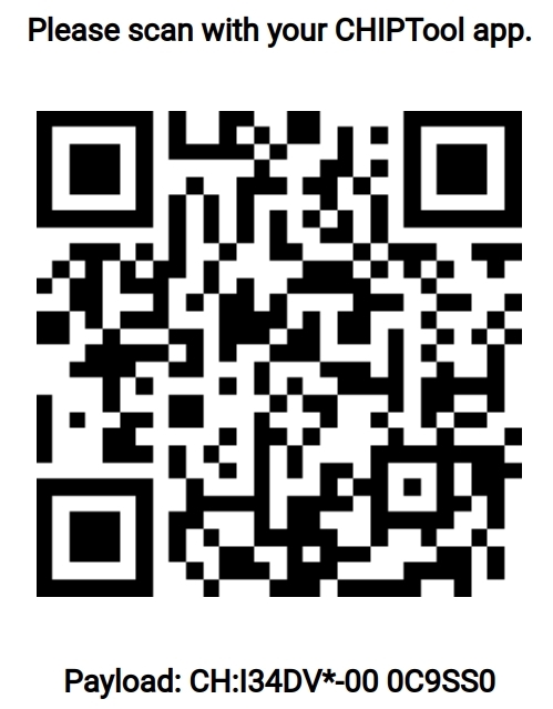
Figure 5. Example QR Code with onboarding payload, generated on the above website.
6. Commissioning accessory device
To commission the accessory device onto the Thread network created in the Forming Thread network section, complete the following steps:
-
Enable Bluetooth and Location services on your smartphone.
-
Connect the smartphone to the Wi-Fi Hotspot created in the Configuring Wi-Fi hotspot section.
-
Open the CHIPTool application on your smartphone.
-
Tap the PROVISION CHIP DEVICE WITH THREAD button and scan the commissioning QR code.
-
You will see a few pop-up messages appear as the commissioning progresses. Eventually, the network settings screen appears.
-
In the new screen tap the Save Network button to send a Thread provisioning message to the accessory device.
You will see the "Network provisioning completed" message when the accessory device successfully joins the Thread network, as presented in the below GIF.
Figure 6. Commissioning accessory device.
7. Sending application packets
After the accessory device is successfully commissioned to the CHIP and Thread networks, it is possible to communicate with it using IP. CHIP uses Zigbee Cluster Library (ZCL) protocol which defines common means for applications to communicate.
To control the simulated Door Lock state, please follow the below steps.
-
Verify that the text box on the next screen contains the IPv6 address of the accessory device.
-
Tap either the ON or the OFF button to lock or unlock the door, respectively.
LED 2 simulates the lock bolt and shows the state of the lock. The following states are possible:
-
Solid On — The bolt is extended and the door is locked.
-
Off — The bolt is retracted and the door is unlocked.
-
Rapid Even Flashing (100 ms on/100 ms off during 2 s) — The simulated bolt is in motion from one position to another.
-
Conclusion
This tutorial presented commissioning and controlling functionalities of the very early development stage of Project CHIP. Using a multiprotocol device such as nRF52840 it is possible to leverage the wide availability of Bluetooth LE technology in our mobile phones for easier set-up, and Thread technology for effective IP connectivity. Lack of out of the shelf generic Thread Border Router with WiFi requires us to create one on our own PC or RaspberryPi which makes setup more difficult. With time, we should see increased number of such products in the market.
We encourage you to follow the ongoing work on the open-sourced repository.
To get more information about the example, platform architecture or CHIP, in general, please visit below pages:
- Main webpage of Connected Home over IP initiative
- The up-to-date documentation of Door Lock example in CHIP repository
- The up-to-date tutorial of commissioning nRF Connect Accessory using Android CHIP Tool
- nRF Connect SDK platform overview

Top Comments
-

Anupam Roy
-
Cancel
-
Vote Up
0
Vote Down
-
-
Sign in to reply
-
More
-
Cancel
-

Damian Krolik
in reply to Anupam Roy
-
Cancel
-
Vote Up
0
Vote Down
-
-
Sign in to reply
-
More
-
Cancel
Comment-

Damian Krolik
in reply to Anupam Roy
-
Cancel
-
Vote Up
0
Vote Down
-
-
Sign in to reply
-
More
-
Cancel
Children