


As the demand for reliable, low-latency, and power-efficient wireless communication grows in IoT and industrial automation, DECT NR+ is quickly emerging as a compelling solution.
While Nordic’s nRF Connect SDK provides the “Hello DECT” sample, implementing IPv6 over NR+, many developers are left wondering how the underlying DECT NR+ API actually works.
In this blog post, we will walk you through a hands-on demo application using two nRF9151 development kits and the latest NR+ firmware (v2.0.0), focusing on the new DLC/MAC API and showing the power saving options available.
Agents to accelerate embedded development. Whether you’re new to DECT NR+ or looking to dig deeper into its API, this guide aims to make the technology, and the development process, more accessible.
Table of Contents
Prerequisites
If you want to duplicate this guide, or play with the code, you will need:
-
NR+ modem firmware (delivered free of charge, just ask your closest friendly Nordic representative)
-
Application software for the demo
-
Nordic Power Profiler Kit II for the power measurements
For how to program the DK’s, please see the DevZone blog: Getting started with NR+ PHY.
NR+ basics
NR+ is an ETSI radio standard for IoT, both for massive mesh networks and low latency communications. It is already seeing growing adaptation in audio use cases and in factory and process automation use cases all of which demand predictable latency and interference free radio channel. Massive networks can be implemented with mesh networking support. For more information on the technology please see the following resources
-
YouTube: The New License-Free IoT Spectrum: In-Depth Investigation into NR+ by Psychogenic Technologies.
Nordic NR+ firmware
Nordic NR+ firmware v2.0.0 comes in two flavors, PHY and DLC/MAC access. Each variant is provided as a separate firmware file and comes with its own distinct API.
The NR+ PHY API offers low-level access, requiring developers to implement their own MAC layer, some aspects of which are necessary for technology certification to operate in the DECT radio band. This approach provides significant flexibility, but also requires more development effort. The DevZone blog post Getting started with NR+ PHY explains the low level PHY access in more detail.
With version 2.0.0, Nordic has introduced a new, higher-level DLC/MAC API, which simplifies development by providing a ready-made MAC protocol layer. The PHY API remains available and is largely unchanged from previous releases. This blog post focuses on the new DLC/MAC API and its power-saving features, which set Nordic’s implementation apart from other NR+ stacks currently available from partners.
Within the NR+ stack, the MAC layer is responsible for network advertisement, link establishment and device association. It serves as the central network management layer, in addition to handling access control. As of version v2.0.0, the Nordic NR+ firmware supports only a star network topology. The central device, referred to as FT (fixed terminal) in NR+ parlance, advertises the network availability with beacons. Child devices, PT devices (portable terminal) in NR+, find the FT beacons, associate to it and then receive information in those beacons when the FT device is listening for the child’s transmission uplink. In the Nordic implementation, the PT devices are not listening all the time for downlink messages from the FT but instead receive a notification in beacons if a message is buffered for the PT device at the FT. The PT will then poll for the message. Uplink transmissions can be fast, if the FT is listening all the time, but downlink is slower, depending on the beacon advertisement period.
This is shown in the sequence graph below
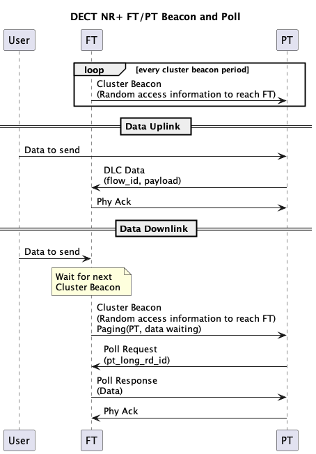 Sequence graph for uplink and downlink send
DLC layer implements segmentation and re-assembly for messages over the MAC link. There are different service levels, transparent sending, acknowledged sending and for the segmentation. In a star network the routing layer of DLC standard is not needed. If a convergence layer is needed, it can be implemented on top of the DECT API in Zephyr.
Architecture of the demo software
The demo software started small and simple to show the beacon period impact and power save operation. But there was a surprising amount of parameters and commands needed. It is a shell-controlled application that provides textual feedback on the shell terminal.
The main point for software development is that the DECT API callbacks are in Interrupt service context (ISR), requiring them to be fast non-blocking operations. To facilitate this the software architecture has a DECT Adapter that maps those callbacks to a message queue for application event handlers to process. The Adapter also hides the DECT specific enumerations from the application.
The software architecture of this demo is shown in the figure below
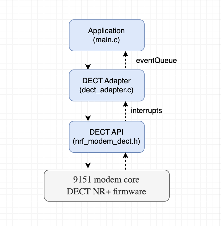 Software architecture
The application handles shell commands, controls the operation and processes the resulting events. There are callbacks on operation completion and application events for data processing notifications from the adapter. The asynchronous operation completion is handled in the prepare_wait, wait_for_prepared_operation and complete_wait functions and semaphores.
The DECT Adapter’s main function is to map the DECT API callbacks into message queue events. This separation prevents dependency leakage and (hopefully) simplifies maintenance.
Device roles and operation
The FT device scans channels (SCAN command) and on user command starts FT beaconing and waiting for associations on a free channel (FT <channel> command). The other device is started in PT mode on the channel (PT <channel>). Currently only one FT and one PT is supported, although it should be simple to add support for more PT devices (association list, show list to direct send to individual device). The user can also scan if there are multiple FT devices and select the wanted FT device (first PT_SCAN, then PT <channel>). FT and PT commands can be given with the channel number (carrier number in NR+ standards) for faster network start and finding and association. With very long beacon periods the advertisement and PT listening on different channels can take considerable time.
In connected mode the device can send messages (SEND <ASCII>) to the other device. There is an additional command STOP to return to initial state and some advanced commands to highlight the operation parameters: PERIOD, POWERSAVE and ACTIVETIME. The period controls the beacon period of the FT device (stop, adjust period and restart, also on PT to adjust the listening period per channel if scanning more channels). POWERSAVE is demonstrated how it impacts the power consumption as measured with the Power Profiler Kit. LIMIT command can be used to try different values when a channel is deemed free or busy.
Main functions
The majority of the functionality is the radio link setup, as shown in the table below
(Recall that FT is the parent and PT is the child device)
|
Function |
Description |
|
nrf_modem_dect_mac_callback_set |
Initialise. Register op and ntf callback structs |
|
nrf_modem_dect_control_systemmode_set |
Initialise. Set DECT system mode (MAC / none) |
|
nrf_modem_dect_control_functional_mode_set |
Initialise. Activate or deactivate the modem |
|
nrf_modem_dect_control_configure |
Initialise. Set TX power, MCS, RSSI target, long RD ID, power save usage configuration |
|
nrf_modem_dect_mac_association |
PT Send association request to FT |
|
nrf_modem_dect_mac_association_release |
Release an existing association |
|
nrf_modem_dect_mac_cluster_beacon_receive |
PT Subscribe to FT cluster beacon |
|
nrf_modem_dect_mac_cluster_beacon_receive_stop |
PT Stop cluster beacon subscription |
|
nrf_modem_dect_mac_cluster_configure |
FT Configure cluster (channel, beacon period, RACH, association limits) |
|
nrf_modem_dect_mac_network_beacon_configure |
FT Configure and start optional network beacon |
|
nrf_modem_dect_mac_network_scan |
PT Scan for FT network and cluster beacons |
|
nrf_modem_dect_mac_network_scan_stop |
PT Stop ongoing network scan |
|
nrf_modem_dect_mac_rssi_scan |
FT Scan RSSI across channels (free channel selection) |
|
nrf_modem_dect_mac_rssi_scan_stop |
FT Stop ongoing RSSI scan |
|
nrf_modem_dect_mac_cluster_info |
Request current cluster info (channel load etc.) |
|
nrf_modem_dect_mac_neighbor_info |
Request info about a specific neighbor by long RD ID |
|
nrf_modem_dect_mac_neighbor_list |
Request list of all known neighbors |
|
nrf_modem_dect_dlc_data_tx |
Transmit DLC data to a neighbor |
|
nrf_modem_dect_dlc_data_discard |
Discard a pending DLC transmission by transaction ID |
Notice there are only two functions for the data transmission: nrf_modem_dect_dlc_data_txand nrf_modem_dect_dlc_data_discard, a discard function to cancel a transmission.
The DLC implementation supports acknowledgements with segmentation and reassembly of messages over the radio link. The rest of the functions establish the radio link. They do initializations, scans and association control. There are operation callbacks and notifications. Notifications are asynchronous modem-initiated callbacks passing data from different events to the higher controlling layer, shown in the table below:
|
control_functional_mode |
Functional mode set operation callback |
|
control_configure |
Configuration operation callback |
|
control_systemmode |
Systemmode set operation callback |
|
association |
Association request callback |
|
association_release |
Association release request callback |
|
cluster_beacon_receive |
Cluster beacon reception request callback |
|
cluster_beacon_receive_stop |
Cluster beacon reception stop request callback |
|
cluster_configure |
Cluster configuration request callback |
|
cluster_info |
Cluster info request callback |
|
neighbor_info |
Neighbor info request callback |
|
neighbor_list |
Neighbor list request callback |
|
dlc_data_tx |
DLC data transmission send callback |
|
dlc_data_discard |
DLC data discard request callback |
|
network_beacon_configure |
Network beacon configuration request callback |
|
network_scan |
Network scan request callback |
|
network_scan_stop |
Network scan stop request callback |
|
rssi_scan |
RSSI scan request callback |
|
rssi_scan_stop |
RSSI scan stop request callback |
|
association_ntf |
FT receives an association request from a PT |
|
association_release_ntf |
Association released by peer or modem |
|
cluster_ch_load_change_ntf |
Cluster channel busy% crosses the configured threshold |
|
neighbor_inactivity_ntf |
A neighbor has been inactive longer than the configured timer |
|
neighbor_paging_failure_ntf |
Paging a neighbor failed |
|
rssi_scan_ntf |
Per-channel RSSI result during an RSSI scan (one per channel) |
|
cluster_beacon_ntf |
A cluster beacon is received over the air |
|
cluster_beacon_rx_failure_ntf |
Consecutive cluster beacon misses exceed configured threshold |
|
ipv6_config_update_ntf |
IPv6 address configuration updated |
|
network_beacon_ntf |
A network beacon is received over the air |
|
capability_ntf |
Modem reports its PHY capabilities (bands, max MCS) |
|
dlc_data_rx_ntf |
DLC data received from a neighbor |
|
dlc_flow_control_ntf |
DLC flow control status change |
It is a bit scary looking (hence our approach with AI Agents) so let’s define the minimal flow for clarity.
The control flow in this demo for the FT device is shown in the figure below, showing the functions called and the state transition events. Association acceptance is automatic if there is memory left in the modem.
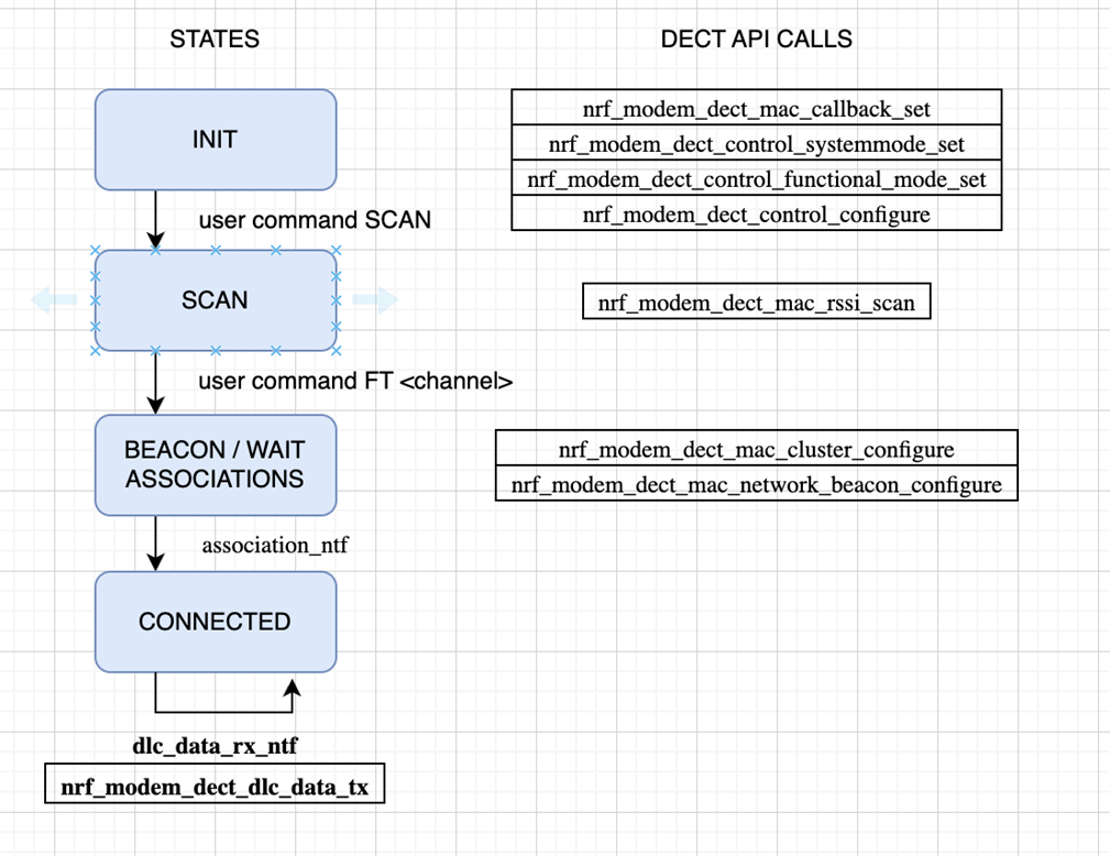 FT flow
The PT flow is shown in the figure below
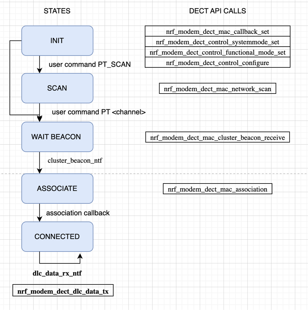 PT flow
There is an optional network scan state, listing found networks (and cluster beacons) on all channels. This was kept for later use of the code. The key thing is to start the beacon receive from the FT and then associate to the FT device. A beacon must be received for the modem to have the radio parameters for how to contact the FT device.
The image below shows a common failure mode. FT tried to send data to the PT, but the PT has dropped out of radio the network so the sending fails.
Note that the timeouts are long, NRF_MODEM_DECT_DLC_SDU_LIFETIME_60_S, those can be controlled in the DECT adapter’s custer_configure_ft and association_request functions with thedlc_sdu_lifetime parameter.
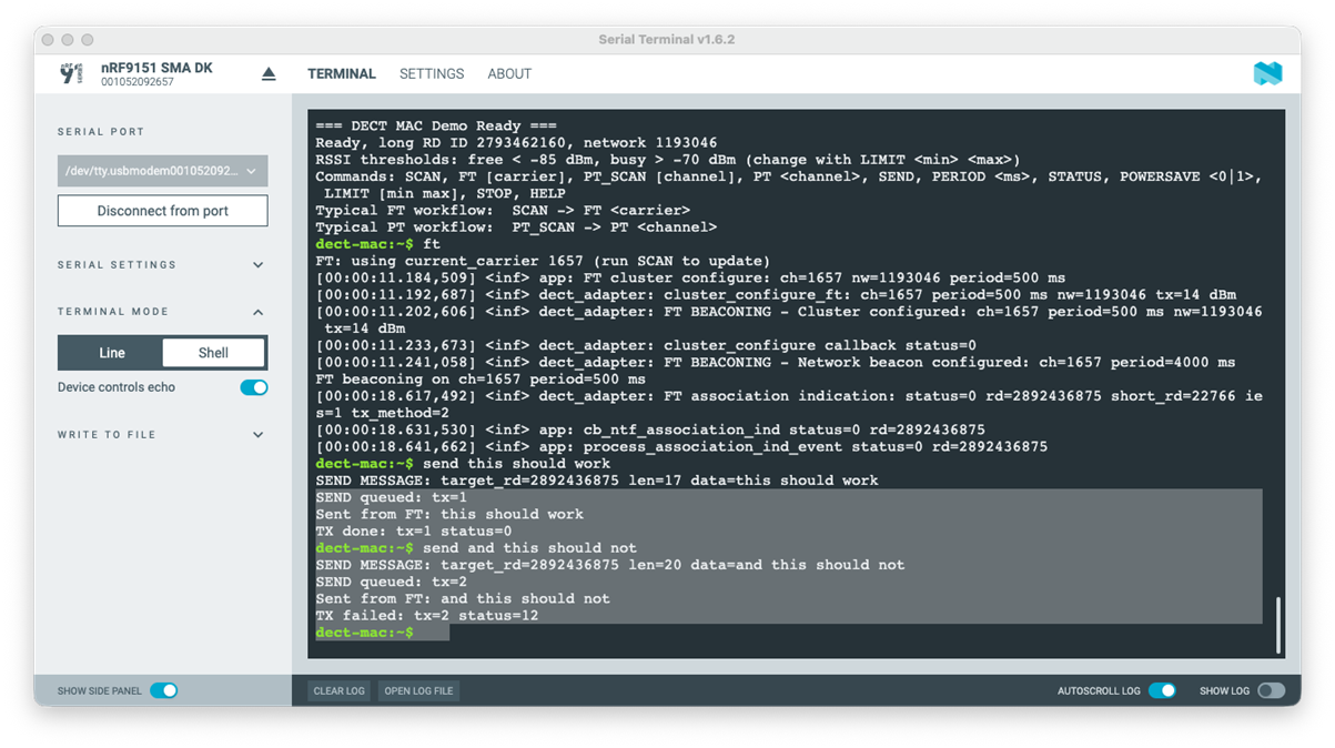
FT showing failed transmission
The FT device is sticky to stay in the beaconing state and accept associations. On the PT side there is fallback (a worker) that is kicked off if there are multiple DLC TX errors, association release or loss of beacon reception. It stops possible ongoing work, re-initializes and associates on the same channel – the assumption is that the FT stays there. This is rudimentary and very poorly tested too!
This re-subscribe is shown in the image below. The key is to check the callbacks status values, and for example the notification cluster_beacon_rx_failure_ntf which signals that the FT signal has not been seen. How soon the notification is fired can be configured in nrf_modem_dect_mac_association_params.

PT recovery from lost beacons
The image below shows retries as done by the modem implementation. There are short Listen-Before-Talk reception peaks, where the channel is being measured to check if it is free for the transmission to start. The higher peaks are the transmission attempts, with increasing power as no response is received. Each TX peak is followed by the ACK listening window. In the end transmission did succeed. If a transmission fails, a failed status is eventually returned in dlc_data_tx callback.
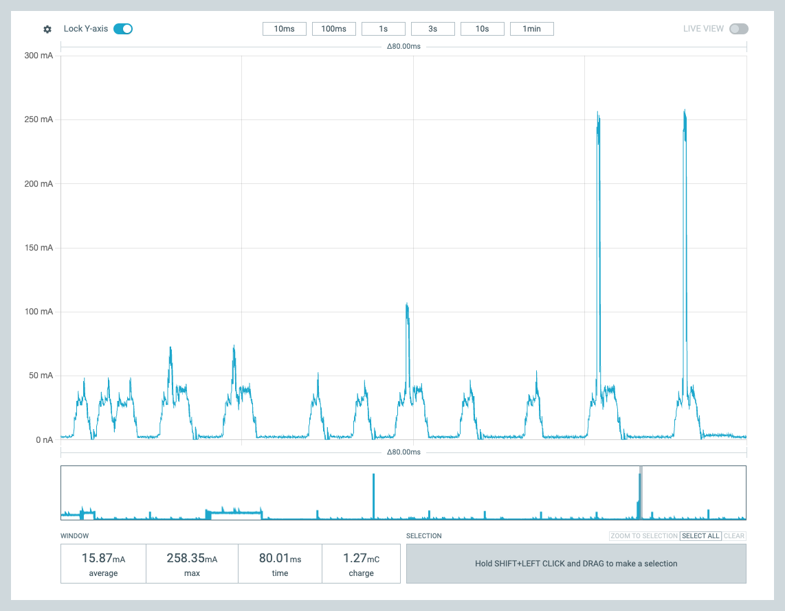 Retries
Power behavior
This demo was developed with the goal of showing the power consumption impact of beacon period control and the power save parameters. Power save command controls the DECT API nrf_modem_dect_control_configure_params.power_save directly. The results of this are presented in this section.
Basic operation, no power save
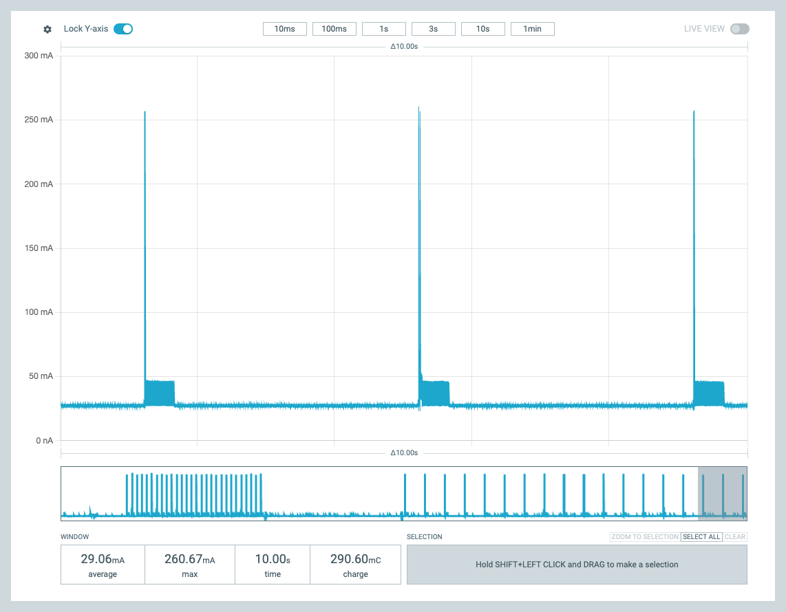
The image below shows the power consumption of the PT device without power save for network scan and association – the high peak. Scan is active listening, at around 50mA power consumption level. Then the association is done, TX peak at 260mA followed by a short response reception window at 50mA. Since this is the first communication, the TX power is not adjusted. After the association period, reception peaks can be seen. These are the beacon receptions from the
FT.
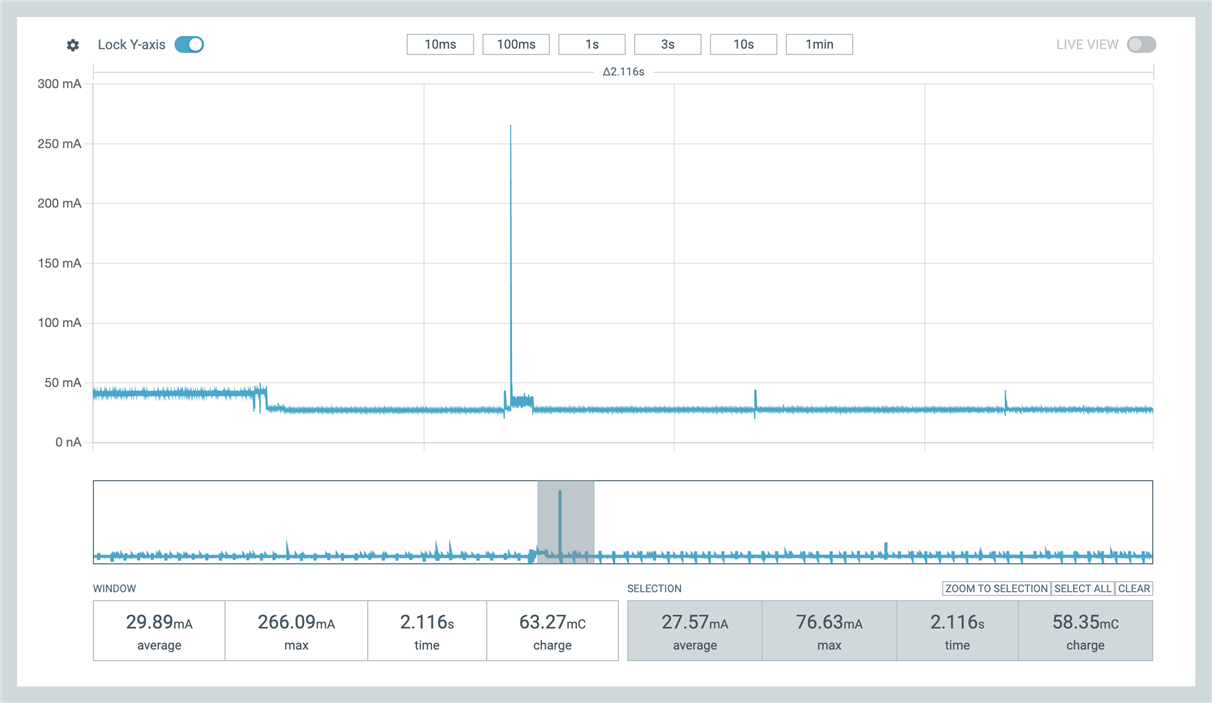
Scan and association, no power save
Power save features in practice
The image below shows similar a association with power save enabled. There is the scan window at around 50mA (and before that the processing of the user command). Association TX peak is once again around 260 mA.
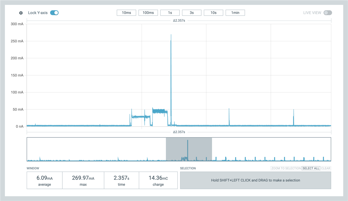
PT association with power save
But after this, the power usage drops significantly, the radio is shut down and power consumption is around 2.2mA as shown in the image below. The application does not implement any power save optimizations and so the application core is running, meaning further power savings are possible. The periodic spikes are once again the beacon reception windows when the radio is powered back on for reception.
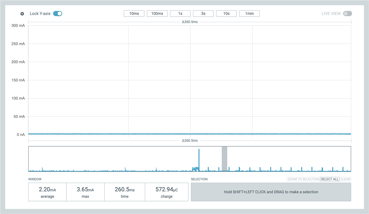
Idle in power save mode
Once in the association state, the TX power can be adjusted. As shown in the image below, the TX peak power usage is controlled, and in this instance is around 70mA. The 50mA peak earlier is the beacon reception window. This TX power adjustment is done based on the nrf_modem_dect_control_configure_params params.expected_mcs1_rx_rssi_level parameter.
The power levels are tracked in association based on reported transmission power in the NR+ PHY header and on the measured reception power. This is then used to calculate the TX power needed to meet the communicated expected level for reception.
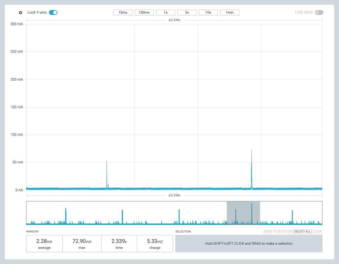
Adjusted send TX power in association
Power save mode on the FT side is also possible, as shown in the image below. The FT beacons are only part of the beacon period, as can be seen in the reception window. The rest of the period, the radio can be powered down. This is controlled with the command ACTIVETIME and is placed in the cluster_config.rach_configuration.config.fill.percentageparameter in the DECT API. The modem implementation then adjusts the advertised random access window that is sent in cluster beacons and the PT devices wait for the next window if sending uplink. This of course impacts the latency for communication.
Note that the FT implementation can not power down the radio as deep as a PT device can; the idle power consumption is not as low as for PT devices.
FT power save
Learnings
AI learning
To me, this was a personal introduction to AI Agent programming. As I understand, AI is a chat sandbox, and an AI Agent can be given permissions to access folders and run commands on the user’s machine. I used Claude, but other AI Agents should work similarly. Based on some guidance from friends and the Internet, I started with this approach:
-
Agent to make itself some new skills
-
Agent to make a Plan (iterate)
-
Agent to generate code from the plan
-
Agent to add feature and test (iterate, update plan, update skills)
It was simple to instruct the AI Agent to create itself some re-usable skills. For example, a build skill using the right west environment and commands – and to flash the merged.hex after some confusion. Also a really useful skill is flashing devices, reset and verifying there is a terminal response. I used nrfutil for that. If there was no response, run nrfutil recover and reflash. “Make a flashing skill, there are 2 devices in USB port that can be programmed with nrfutil command”.
The AI could also run a test script, to give the command and look for the correct response from the devices. I believe these skills are largely AI Agent independent, seemed to be markdown documentation and bash and python scripts, but of course heavily dependent on the host computer and environment.
The planning phase seems essential. The plan is a markdown document, edited by me and the Agent. What commands to do, what HW is used, what nRF Connect SDK version and so on. An architecturally significant requirement is the ISR-context protection with the event queue. In planning, the AI also asks clarifications and builds better context for the task. The code generation is done in a second, but still the developer needs time to understand it. I fear to think what would have been the output without planning, and how many iterations and code reviews it would have taken. Asking about an issue can automatically generate fix change in code, and not always in the right place. I learned to ask for “analysis no fix”. Maybe it was test driven design I ended up using, adding operations and commands one at a time and checking the outcome after the initial plan implementation.
At times the Agent felt so human, noticing missing error code handling or dead code from an earlier change. To me it was surprising that the Agent might fix an issue but sometimes leave dead code and parameters into the source files. So human! It is good to ask the Agent to analyze the code for weaknesses and dead code every now and then.
I was surprised how easy it was to hit the usage limits. And the Agent can stop in the middle of a change being done -- this is not nice for a developer. I strongly recommend a paid subscription, but even then there are limits that are all too easy to hit as I learned. This was worsened by the skills usage, that makes the Agent process more messages and data than strictly needed as it also parsed the outputs. Of course, skills are bash scripts so running them by hand is an option, but it is so much easier to command “build, flash and test”.
The real learning for me was to improve the header documentation in the future. For example, if the function is for specific role, or if the function starts generating notifications or events and what is the actual flow of separate function calls. When we work with the technology we easily assume everybody knows this, but an AI Agent for sure does not know. But I got surprisingly good results after I made it analyze the sample application and libraries in the SDK.
Other learning
A mysterious USB dependency had me puzzled for a long time. Seems that a display that acts as a USB hub impacts the USB speed also of more directly connected devices. I was stuck when the software worked at home, but not at work. Then removing the external display at work, that acts as a USB hub too, brought the operation back to what I was seeing at home. The devices are in both cases connected with an external USB adapter. Speed configuration changes on the PC USB controller when the display is added? Of course, this also strongly hints at the weakness of my code.
Closing
In summary, this project aimed to not only demystify the DECT API, but also highlight the evolving role of AI Agents in embedded development. By combining hands-on experimentation with the nRF9151 DK and leveraging AI-driven planning and automation, both the technical implementation and the learning process was simplified.
I hope this walkthrough helps others get started with DECT NR+ and inspires confidence in using AI Agents as collaborative partners in future embedded projects.
