

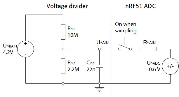
Here is an example of a hardware setup to measure the voltage on a Lithium battery with a voltage divider and a connected capacitor. The Lithium battery typically has a voltage range of 2.7 - 4.2 V and we (Nordic) recommend that you divide the battery voltage with two resistors, R1 = 10 MΩ and R2 = 2.2 MΩ. After you do this you need to connect a 22 nF capacitor (C2 in the figure below) from your ADC analog input pin (AIN) to ground. With this configuration you can sample up to 20 Hz for 8-bit sampling and up to 8 Hz for 10-bit sampling without noticeable ADC output error. You should use the internal VBG voltage as reference (it’s fixed to 1.2 V), and no input prescaling (1/1).
The ADC example code found here samples from analog input pin 6 and is set up for the hardware configuration mentioned above. This example outputs the ADC sampled result to port 1, i.e. pins 8-15.
With this setup the voltage divider consumes current of 4.2 V / (12,2 MΩ) = 0.35 uA.
Usable ADC resolution
The reason behind the specific voltage divider setup described above is to have the voltage on the ADC AIN input pin as close to 0.6 V as possible. This ensures that the current flowing in and out of the ADC is minimal and you can use a small capacitor. If the voltage on the ADC AIN pin is 0.6 V, then there is no current flowing into the ADC because the internal voltage source of the ADC is also VBG/2 = 1.2 V/2 = 0.6 V. If we assume that the voltage range of the Lithium battery is 2.7 V - 4.2 V, i.e. 2.7 V when empty and 4.2 V when fully charged, then the voltage range on the ADC AIN input pin is:
- Maximum voltage: 4.2 V * (2.2 M/(2.2 M+10 M)) = 0.757 V
- Minimum voltage: 2.7 V * (2.2 M/(2.2 M+10 M)) = 0.487 V
- ADC value at 4.2 V - 10 bit setup: 0.757 V/1.2*1023 = 646
- ADC value at 2.7 V - 10 bit setup: 0.487 V/1.2*1023 = 415
- Usable ADC resolution - 10 bit setup: 646-415 = 231
It’s useful to increase the ADC resolution for measuring the battery voltage more accurately. This can be done by choosing a smaller resistance value for the R1 resistor in the voltage divider. By choosing a smaller resistor for R1, a larger capacitor is needed because there will be more current flowing into the ADC while sampling, which will further limit the maximum ADC sampling frequency. As an example, if the value of R1 is 6 MΩ, then the usable ADC resolution would be:
- Maximum voltage: 4.2 V * 2.2 M/(2.2 M+6 M) = 1.126 V
- Minimum voltage: 2.7 V * 2.2 M/(2.2 M+6 M) = 0.724 V
- ADC value at 4.2 V - 10 bit setup: 1.126/1.2*1023 = 961
- ADC value at 2.7 V - 10 bit setup: 0.724/1.2*1023 = 617
- Usable ADC resolution - 10 bit setup: 961 - 617 = 344
Determine capacitor size
With the voltage divider setup above and R1=6MΩ instead of 10MΩ, a good capacitor value would be around 100 nF for 10 bit sampling and the sampling frequency should not be higher than 2 Hz.
To determine the size of a suitable capacitor for a custom voltage divider the calculation method given on this thread can be used. It should calculate a suitable size for the capacitor so that less than 1 bit error is observed on the ADC output for a specific sampling frequency range. However, often the easiest way to determine a suitable capacitor size for a custom voltage divider or any connected external circuit with impedance higher than 1kΩ, is to use trial and error method. Start with mounting e.g. 100 nF capacitor between the ADC input pin and ground. If you do not get adequate ADC accuracy with low sample rate (<1Hz), increase the size until error disappears. The trade-off is that if you have large capacitor, the maximum sampling frequency is lower then when you have a small capacitor. Typically you are limited to 1Hz - 10Hz maximum sampling frequency when using a capacitor.

Top Comments