

In December we published a video showing a long range test with the newly released nRF52840 chip. The video showed that the nRF52840 had excellent range, and is fully compatible with the new Long Range feature of the just released Bluetooth 5 specification. This blogpost will go into more details about how this test was done. Below is the video for those that have not seen it yet.
The setup consisted of two nRF52840 Preview Development kits, one transmitter (TX) and one receiver (RX). Both kits were connected to a GPS module using serial communication (UART). The DK on the receiving end also had a display shield developed here at Nordic and was connected to a computer. On the computer a program was displaying the different RF parameters like TX ouput power, on air bitrate and Link Budget, and the received data like the distance between the kits, the Receiver Signal Strength Indicator (RSSI) and the GPS coordinates of both kits. The display shield also showed this information along with info about how to change the different parameters; tx output power and bitrate. The different parameters were simply changed by using the buttons on the development kit.
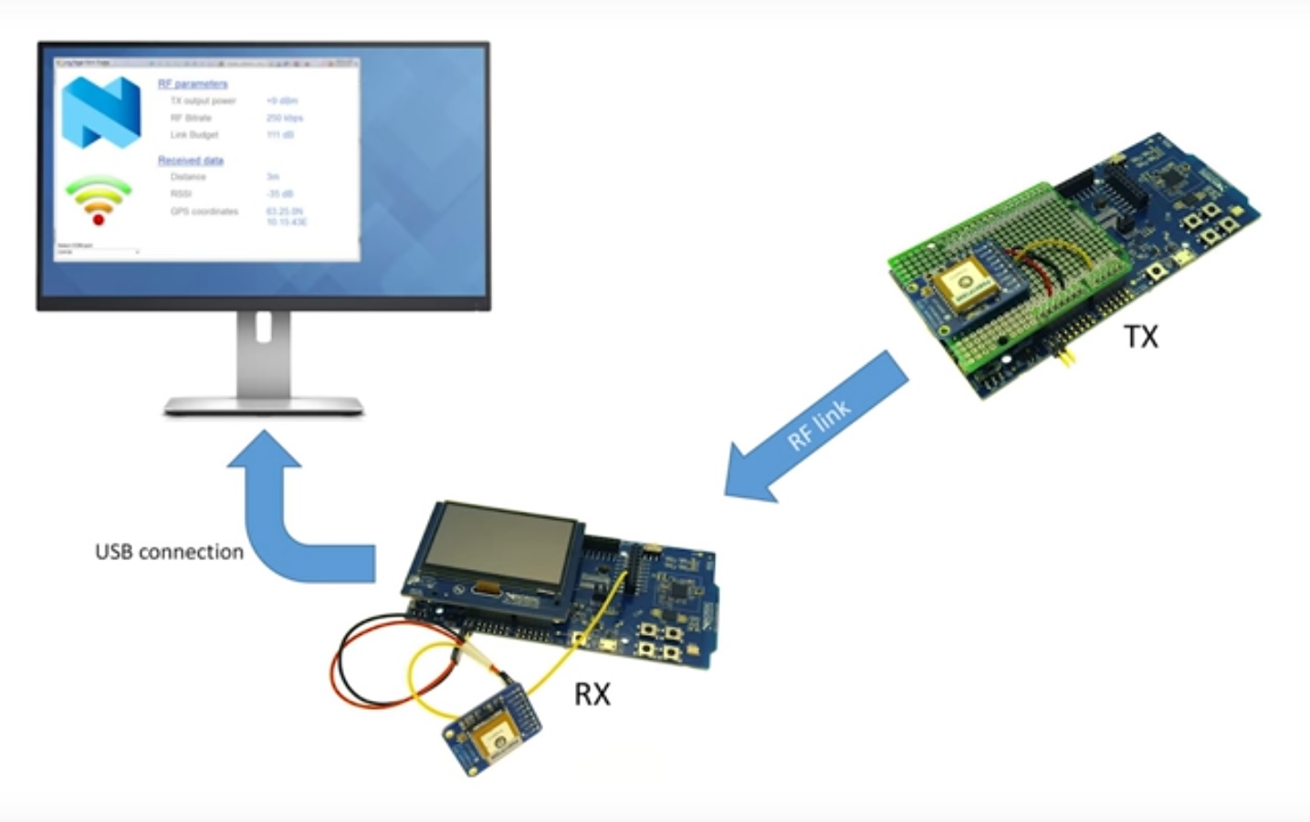
The GPS modules output the data over UART as [NMEA data] (https://en.wikipedia.org/wiki/NMEA_0183). This data includes among others the time, latitude and longitude position, number of satellites used and altitude. You can read more about it in Sparkfuns GPS guide. The transmitter (the kit that was attached to the drone) stripped down the message from the GPS module to only include the relevant information and sent it to the receiver (the kit connected to the PC). The receiver then calculated the distance between the kits based on the received data from the transmitter and the data from its own GPS module. The distance was calculated using the same formulas as described here (only using C instead of Javascript).
The communication was done using the radio directly (no SoftDevice), with settings for 125 kbps Long Range mode. Data was sent in one direction with no ACKing. This is more or less the same as if we had used Bluetooth advertising with 125 kbps Long Range mode, one of the differences being that only one channel was used.
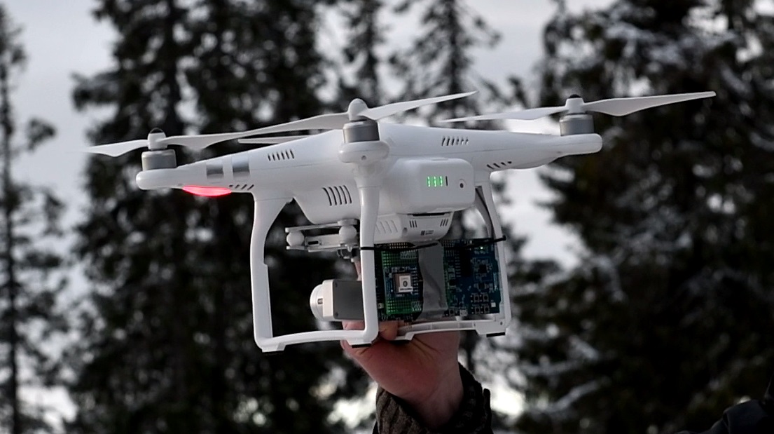
As shown in the video two tests were conducted. In the first test the output power was set to 4 dBm and the bitrate was set to 1 Mbit. This is the settings that would give the best range on the prior chip, the nRF52832, without using an external Power Amplifier (PA). The transmitter was then brought about 100 meters down range and the connection (RSSI) was still good. To get any further we needed something to carry the development kit a long way while still having the kit in line of sight. For this we used a quadcopter/drone – a remotely controlled helicopter with four rotors. The quadcopter was of the type DJI Phantom 2. The transmitter was mounted on the quadcopter legs using cable ties. For this test we turned the output power up to 8 dBm and the bitrate down to 125 kbps. This is the settings that gives the highest link budget on the nRF52840 and thereby the longest range.
The second test we ran two times. The second time the drone was at one point almost 800 meters away from our “station” and we still had good connection with RSSI values of between -80 and -90 dBm. The reason we did go longer was that the pilot did not want to fly any further away because of the equipment and that he did not have a license for flying directly using the camera, which meant that he had to be able to see the drone at all times.
The test showed that under good conditions we can get much improved range with the nRF52840. The specified sensitivity for 125 kbps Bluetooth Low Energy Long Range mode is at -103 dBm (see the Product Specification), which means that there is in theory still over 12 dBm left. As a rule of thumb 6 dBm difference equals double the distance, so we should theoretically be able to go at least 4 times longer. Next time we do a range test we will make sure that we have the correct equipment to go even further than this time, so stay tuned for a new long range test with even longer range!
For those of you who wants to try it out for yourself, here are the hex files for the transmitter (ptx) and receiver (prx):
nRF52840_long_range_demo_prx.hex
nRF52840_long_range_demo_ptx.hex
The GPS coordinates, distance between the kits and RSSI is printed using RTT. Connect the RTT viewer to the receiver (prx) kit. If the GPS does not have location fix, "no fix" will be printed out and the distance cannot be measured. If this is the case you should take the GPS module to a more open area to get location fix.
UART TX on the GPS module is connected to P1.09 on the receiver (prx) and to P0.04 on the transmitter (ptx). Vin on the GPS module is connected to VDD and GND to GND.

Top Comments
-

jatkinsaut
-
Cancel
-
Vote Up
0
Vote Down
-
-
Sign in to reply
-
More
-
Cancel
Comment-

jatkinsaut
-
Cancel
-
Vote Up
0
Vote Down
-
-
Sign in to reply
-
More
-
Cancel
Children