Introduction
Using proprietary protocols can be an effective way of addressing shortcomings in BLE. When communicating between two nRF chips, one can for example use a different packet format or different symbol rate to improve throughput or increase range.
Getting started with micro-ESB on nRF51 discusses the ESB protocol and the micro-ESB implementation specfically. Now we will look at how one can run a protocol such as ESB concurrently (interleaved) with BLE (or ANT) by leveraging the Timeslot feature of the nRF5x SoftDevices.
Timeslot API
The Timeslot API allows the application to request slots of uninterrupted time. During these timeslots, the application has access to all hardware, including the radio. We can use these timeslots to run the ESB protocol for example. This opens up some interesting opportunities, as nRF chips can communicate among themselves using a more specialized protocol without breaking BLE connections with other devices.
The "Concurrent Multiprotocol Timeslot API" section of the SoftDevice Specification document describes this feature in more detail, and it's strongly recommended to read before proceeding.
The Setting up the timeslot API tutorial is also worthwhile to look at, as this looks at the API in more detail than this blog post.
Timeslot basics
When the application requests a timeslot, it has the following parameters to play with:
- When should the timeslot begin
- How long should the timeslot last
- What is the priority of the request
One can ask for a timeslot to begin at a specific time, for example "2500 microseconds from now", or simply "as soon as possible".
Furthermore, one can request an extension to an ongoing timeslot. This is a useful feature we will use to keep scanning for as much of the time as possible.
Figure 10 from the S110 SoftDevice Specification document illustrates how the timeslot extensions work (again, it's recommended to read this document).
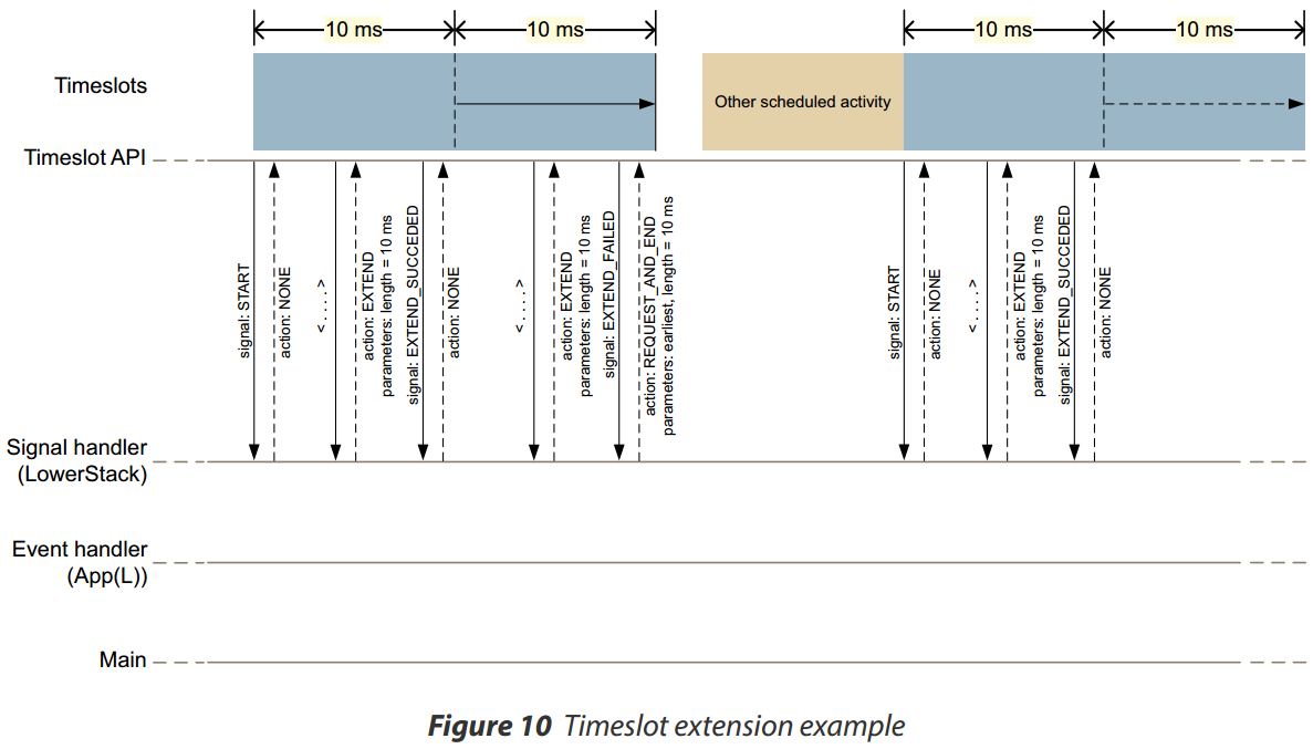
This figure illustrates another important aspect of the timeslots. Timeslot signals are generated in the highest interrupt priority (LowerStack priority). As such, care must be taken to ensure correct behavior when used in your application.
Adapting micro-ESB to timeslots
Some work must be done in order to get micro-ESB working concurrently with BLE (or ANT). The best approach depends on the specific application, requirements for power, latency, and so on. The approach presented here is intended to be as simple as possible.
ESB basics
ESB is a fairly simple link layer. It has two main roles: the Primary Transmitter (PTX) and the Primary Receiver (PRX). The PTX sends packets to the PRX, and the PRX acknowledges these packets. Data can be sent two ways either by piggybacking data in the ACK packets from the PRX, or by switching roles whenever needed.
ESB application
Just like in Getting started with micro-ESB on nRF51 we'll implement a wireless UART application, where the nRF51 acts as a bridge between a wired UART interface and a wireless one. Like in the previous blog post, the wireless interface will include ESB. But this time we will include a BLE interface as well, using the UART Service.
ESB behavior
To keep it simple, we won't do any channel hopping or time synchronization. Adding these things does increase co-existence performance and reduce power consumption, but it adds a lot of complexity. Instead the application will normally be in PRX mode, listening for packets on a single RF channel.
To maximize the chances of the PRX picking up packets transmitted by the PTX, we will try to use all remaining radio time. Whenever a timeslot gets rejected due to a scheduling conflict with BLE we'll request a new one. When data is received on the wired UART interface, we'll switch role to PTX and transmit the data.
The state machine figure below illustrates the flow of timeslot requests.
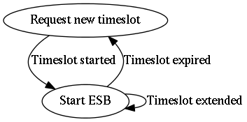
Note that there is no synchronization between the ESB devices, so there's no guarantee both devices won't switch to the PTX role at the same time. But in this example, performance isn't a consideration.
Playing nice
It's important to note that it's the applications responsibility to ensure that radio activity has finished by the time the timeslot ends. This means we should start shutting down ESB a couple of hundred microseconds prior to the timeslot ending, just to leave room for corner cases where the peer PTX starts sending just as the timeslot ends. Similarly, we'll only start transmitting packets (in the PTX role) in the beginning of a timeslot to ensure the timeslot won't end in the middle of a transfer. The maximum number of retransmissions we can use for ESB will thus be a function of packet length and timeslot duration.
The figure below illustrates the slight modification to the PRX and PTX mode switching criteria compared to the original blog post.

We don't have to revert the radio configuration registers once the timeslot ends, but we do have to re-configure them in the beginning of a timeslot. Extending a timeslot does not alter the configuration in any way, as this is just a continuation of the already ongoing timeslot.
Setting up the code
We will use ble_app_uart as a starting point, as this BLE Peripheral example has all of the BLE basics as well as the UART Service already set up.
Debug printouts
We'll be using UART not only for doing the wired-to-wireless bridge functionality, but also for debug printouts. The nRF51-DK has a USB interface with a virtual COM port, which makes it easy to retrieve the UART output using a terminal application on your development platform.
COM port settings should be the following:
- 1 MBaud
- 8 data bits, 1 stop bit
- No parity
- Hardware flow control (RTS/CTS) enabled
Interrupt priority management
As mentioned, timeslot signals/callbacks are generated at the highest interrupt priority. To avoid race conditions, deadlocks, and other hard-to-debug issues we'll use a few software-triggered interrupts to reduce the priority whenever dealing with shared data or ESB configuration. Any unused IRQHandler can be used for this purpose, as we'll only trigger the interrupts from software without dealing with any hardware:
#define TIMESLOT_BEGIN_IRQn        LPCOMP_IRQn
#define TIMESLOT_BEGIN_IRQHandler  LPCOMP_IRQHandler
#define TIMESLOT_BEGIN_IRQPriority 1
#define TIMESLOT_END_IRQn          QDEC_IRQn
#define TIMESLOT_END_IRQHandler    QDEC_IRQHandler
#define TIMESLOT_END_IRQPriority   1
#define UESB_RX_HANDLE_IRQn        WDT_IRQn
#define UESB_RX_HANDLE_IRQHandler  WDT_IRQHandler
#define UESB_RX_HANDLE_IRQPriority 3
TIMESLOT_BEGIN_IRQn is used to enable ESB at the beginning of a timeslot, TIMESLOT_END_IRQn for cleanup at the end of one, and UESB_RX_HANDLE_IRQn is used to notify of received data.
Timeslot initialization
The first step is to open a timeslot session, essentially preparing the softdevice for the requests to come. This is done using sd_radio_session_open(), where we also provide a callback function for handling timeslot signals. Once a session has been opened, timeslots can be requested using sd_radio_request().
uint32_t ut_start(uint32_t rf_channel, uint8_t rf_address[5], fifo_t * p_recv_fifo)
{
    uint32_t        err_code;

    if (m_timeslot_session_open)
    {
        return NRF_ERROR_INVALID_STATE;
    }

    if (p_recv_fifo == 0)
    {
        return NRF_ERROR_INVALID_PARAM;
    }

    m_uesb_config.rf_channel = rf_channel;
    memcpy(m_uesb_config.rx_address_p0, rf_address, 5);

    m_receive_fifo             = p_recv_fifo;
    m_timeslot_is_active       = false;
    m_blocked_cancelled_count  = 0;

    err_code = sd_radio_session_open(radio_callback);
    if (err_code != NRF_SUCCESS)
    {
        return err_code;
    }

    err_code = sd_radio_request(&m_timeslot_req_earliest);
    if (err_code != NRF_SUCCESS)
    {
        return err_code;
    }

    m_timeslot_session_open = true;

    return NRF_SUCCESS;
}
Handling timeslot signals
The callback we provided when opening the timeslot allows us to handle the various signals generated by the softdevice. These signals are listed in nrf_soc.h:
/**@brief The Radio signal callback types. */
enum NRF_RADIO_CALLBACK_SIGNAL_TYPE
{
  NRF_RADIO_CALLBACK_SIGNAL_TYPE_START,             /**< This signal indicates the start of the radio timeslot. */
  NRF_RADIO_CALLBACK_SIGNAL_TYPE_TIMER0,            /**< This signal indicates the NRF_TIMER0 interrupt. */
  NRF_RADIO_CALLBACK_SIGNAL_TYPE_RADIO,             /**< This signal indicates the NRF_RADIO interrupt. */
  NRF_RADIO_CALLBACK_SIGNAL_TYPE_EXTEND_FAILED,     /**< This signal indicates extend action failed. */
  NRF_RADIO_CALLBACK_SIGNAL_TYPE_EXTEND_SUCCEEDED   /**< This signal indicates extend action succeeded. */
};
Note that two of the signals are interrupts being forwarded for the RADIO and TIMER0 hardware peripherals. We will use TIMER0 to keep track of the timeslot duration, such that we can request a timeslot extension before the ongoing timeslot ends, and if that fails shut down micro-ESB before the timeslot ends. Remember it's the applications responsibility to make sure all radio operations has stopped by the time the timeslot ends.
This is what the signal handler looks like:
/**@brief   Function for handling timeslot events.
 */
static nrf_radio_signal_callback_return_param_t * radio_callback (uint8_t signal_type)
{
    // NOTE: This callback runs at lower-stack priority (the highest priority possible).
    switch (signal_type) {
    case NRF_RADIO_CALLBACK_SIGNAL_TYPE_START:
        // TIMER0 is pre-configured for 1Mhz.
        NRF_TIMER0->TASKS_STOP          = 1;
        NRF_TIMER0->TASKS_CLEAR         = 1;
        NRF_TIMER0->MODE                = (TIMER_MODE_MODE_Timer << TIMER_MODE_MODE_Pos);
        NRF_TIMER0->EVENTS_COMPARE[0]   = 0;
        NRF_TIMER0->EVENTS_COMPARE[1]   = 0;
        NRF_TIMER0->INTENSET            = (TIMER_INTENSET_COMPARE0_Set << TIMER_INTENSET_COMPARE0_Pos) |
                                          (TIMER_INTENSET_COMPARE1_Set << TIMER_INTENSET_COMPARE1_Pos);
        NRF_TIMER0->CC[0]               = (TS_LEN_US - TS_SAFETY_MARGIN_US);
        NRF_TIMER0->CC[1]               = (TS_LEN_US - TS_EXTEND_MARGIN_US);
        NRF_TIMER0->BITMODE             = (TIMER_BITMODE_BITMODE_24Bit << TIMER_BITMODE_BITMODE_Pos);
        NRF_TIMER0->TASKS_START         = 1;

        NRF_RADIO->POWER                = (RADIO_POWER_POWER_Enabled << RADIO_POWER_POWER_Pos);

        NVIC_EnableIRQ(TIMER0_IRQn);
        break;

    case NRF_RADIO_CALLBACK_SIGNAL_TYPE_TIMER0:
        if (NRF_TIMER0->EVENTS_COMPARE[0] &&
           (NRF_TIMER0->INTENSET & (TIMER_INTENSET_COMPARE0_Enabled << TIMER_INTENCLR_COMPARE0_Pos)))
        {
            NRF_TIMER0->TASKS_STOP  = 1;
            NRF_TIMER0->EVENTS_COMPARE[0] = 0;

            // This is the "timeslot is about to end" timeout

            // Disabling UESB is done in a lower interrupt priority
            NVIC_SetPendingIRQ(TIMESLOT_END_IRQn);

            // Schedule next timeslot
            return (nrf_radio_signal_callback_return_param_t*) &m_rsc_return_sched_next;
        }

        if (NRF_TIMER0->EVENTS_COMPARE[1] &&
           (NRF_TIMER0->INTENSET & (TIMER_INTENSET_COMPARE1_Enabled << TIMER_INTENCLR_COMPARE1_Pos)))
        {
            NRF_TIMER0->EVENTS_COMPARE[1] = 0;

            // This is the "try to extend timeslot" timeout

            if (m_total_timeslot_length < (128000000UL - 1UL - TX_LEN_EXTENSION_US))
            {
                // Request timeslot extension if total length does not exceed 128 seconds
                return (nrf_radio_signal_callback_return_param_t*) &m_rsc_extend;
            }
            else
            {
                // Return with no action request
                return (nrf_radio_signal_callback_return_param_t*) &m_rsc_return_no_action;
            }
        }


    case NRF_RADIO_CALLBACK_SIGNAL_TYPE_RADIO:
        // Call the uesb IRQHandler
        RADIO_IRQHandler();
        break;

    case NRF_RADIO_CALLBACK_SIGNAL_TYPE_EXTEND_FAILED:
        // Don't do anything. Our timer will expire before timeslot ends
        return (nrf_radio_signal_callback_return_param_t*) &m_rsc_return_no_action;

    case NRF_RADIO_CALLBACK_SIGNAL_TYPE_EXTEND_SUCCEEDED:
        // Extension succeeded: update timer
        NRF_TIMER0->TASKS_STOP          = 1;
        NRF_TIMER0->EVENTS_COMPARE[0]   = 0;
        NRF_TIMER0->EVENTS_COMPARE[1]   = 0;
        NRF_TIMER0->CC[0]               += (TX_LEN_EXTENSION_US - 25);
        NRF_TIMER0->CC[1]               += (TX_LEN_EXTENSION_US - 25);
        NRF_TIMER0->TASKS_START         = 1;

        // Keep track of total length
        m_total_timeslot_length += TX_LEN_EXTENSION_US;

        // UESB packet receiption and transmission are synchronized at the beginning of timeslot extensions.
        // Ideally we would also transmit at the beginning of the initial timeslot, not only extensions,
        // but this is to simplify a bit.
        NVIC_SetPendingIRQ(TIMESLOT_BEGIN_IRQn);
        break;

    default:
        app_error_handler(MAIN_DEBUG, __LINE__, (const uint8_t*)__FILE__);
        break;
    };

    // Fall-through return: return with no action request
    return (nrf_radio_signal_callback_return_param_t*) &m_rsc_return_no_action;
}
And the micro-ESB handling, which is done at a lower interrupt priority:
/**@brief IRQHandler used for execution context management.
  *        Any available handler can be used as we're not using the associated hardware.
  *        This handler is used to stop and disable UESB
  */
void TIMESLOT_END_IRQHandler(void)
{
    uint32_t err_code;

    // Timeslot is about to end: stop UESB

    err_code = uesb_stop_rx();
    if (err_code != UESB_SUCCESS)
    {
        // Override
        NRF_RADIO->INTENCLR      = 0xFFFFFFFF;
        NRF_RADIO->TASKS_DISABLE = 1;
    }

    uesb_disable();

    m_total_timeslot_length = 0;
}

/**@brief IRQHandler used for execution context management.
  *        Any available handler can be used as we're not using the associated hardware.
  *        This handler is used to initiate UESB RX/TX
  */
void TIMESLOT_BEGIN_IRQHandler(void)
{
    uesb_payload_t payload;
    uint32_t       payload_len;
    uint32_t       err_code;

    uesb_init(&m_uesb_config);

    // Packet transmission is syncrhonized to the beginning of timeslots
    // Check FIFO for packets and transmit if not empty
    if (m_transmit_fifo.free_items < sizeof(m_transmit_fifo.buf) && m_ut_state != UT_STATE_TX)
    {
        // There are packets in the FIFO: Start transmitting
        payload_len = sizeof(payload);

        // Copy packet from FIFO. Packet isn't removed until transmissions succeeds or max retries has been exceeded
        if (m_tx_attempts < MAX_TX_ATTEMPTS)
        {
            fifo_peek_pkt(&m_transmit_fifo, (uint8_t *) &payload, &payload_len);
            APP_ERROR_CHECK_BOOL(payload_len == sizeof(payload));
        }
        else
        {
            fifo_get_pkt(&m_transmit_fifo, (uint8_t *) &payload, &payload_len);
            APP_ERROR_CHECK_BOOL(payload_len == sizeof(payload));

            m_tx_attempts = 0;
        }

        if (m_ut_state == UT_STATE_RX)
        {
            uesb_stop_rx();
        }

        err_code = uesb_write_tx_payload(&payload);
        APP_ERROR_CHECK(err_code);

        m_ut_state = UT_STATE_TX;
    }
    else
    {
        // No packets in the FIFO: start reception
        err_code = uesb_start_rx();
        m_ut_state = UT_STATE_RX;

    }
}

/**@brief IRQHandler used for execution context management.
  *        Any available handler can be used as we're not using the associated hardware.
  *        This handler is used to notify of received data
  */
void UESB_RX_HANDLE_IRQHandler(void)
{
    uesb_payload_t payload;
    uint32_t       err_code;

    // Get packet from UESB buffer
    uesb_read_rx_payload(&payload);

    // Give packet to main application via the scheduler
    err_code = app_sched_event_put(payload.data, payload.length, m_evt_handler);
    APP_ERROR_CHECK(err_code);
}
The above code is organized as a library, uesb_timeslot, with the following API:
/**@brief Initialize UESB Timeslot library
 *
 * @note app_scheduler is used to execute the event handler, and must be initialized before calling @ref ut_start
 *
 * @param[in] evt_handler Event handler for received data
 * @retval NRF_SUCCESS
 * @retval NRF_INVALID_PARAM
 */
uint32_t ut_init(ut_data_handler_t evt_handler);

/**@brief Start requesting timeslots to run micro-ESB
 *
 * @param[in] rf_channel RF channel to use [0-80]. Must be the same for both devices.
 * @param[in] rf_address Packet address to use. Must be the same for both devices.
 *
 * @retval NRF_SUCCESS
 * @retval NRF_ERROR_INVALID_STATE
 */
uint32_t ut_start(uint32_t rf_channel, uint8_t rf_address[5]);

/**@brief Send string via micro-ESB
 *
 * @note Function blocks until previous transmission has finished
 * @details String is put into internal buffer. Transmission will be started at the beginning of the next timeslot or timeslot extension.
 * @param[in] p_str  String
 * @param[in] length String length
 *
 * @retval NRF_SUCCESS
 * @retval NRF_ERROR_NO_MEM
 */
uint32_t ut_send_str(uint8_t * p_str, uint32_t length);

/**@brief SoftDevice system event handler. Must be called when a system event occurs */
void ut_on_sys_evt(uint32_t sys_evt);
Note that app_scheduler is used to dispatch data received events from the library.
Running the code
The attached code is compiled and tested with the following components:
- nRF51 SDK 9.0.0
- S130 1.0.0
- 2 x nRF51-DK
- Keil 5.12
- GCC 4.9 2015q1
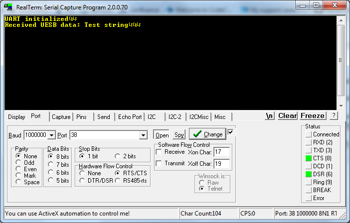
After compiling the code, use a serial terminal to verify that the code is running. Any asserts or error codes will also be printed out:
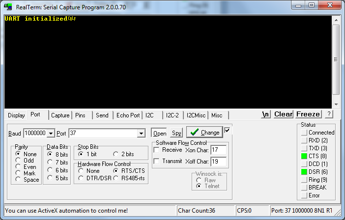
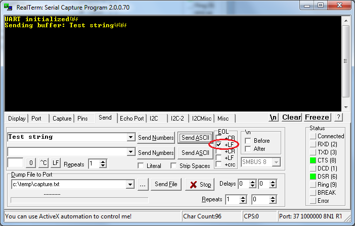
Write a string to the COM port to further verify the setup. Note the EOL character:
Running the code on a 2nd nRF51-DK gives the following printout:
In terms of BLE behavior, the code behaves just like the standard UART Service example. Use for example the UART functionality of nRF Toolbox for Android, iOS, or Windows phone to connect to the nRF51-DK and transmit strings back and forth.
Strings written to the COM port will be transmitted both over BLE and micro-ESB. Strings received on either protocol will be printed out to the COM port
Attachments
Code available on github: https://github.com/NordicSemiconductor/nrf51-ble-micro-esb-uart


Top Comments