


This blog post describes how you can take advantage of the 4 MOSFET's on the Thingy:52.
DISCLAIMER: Please verify all information that is used/retrieved from this blog post. Some of the information might be inaccurate as this blog post has not been reviewed by anyone besides,, well, myself :D
"For more flexibility, Thingy is equipped with four N-MOS transistors that can be used to drive small DC motors or LEDs. The drain and source of the transistors are available on external connectors and the gate is connected directly to the nRF52832.", ref https://www.nordicsemi.com/DocLib/Content/User_Guides/thingy52/latest/UG/thingy52/hw_description/hw_transistors.
- Thingy:52 v1.0.0, https://www.nordicsemi.com/Software-and-Tools/Development-Kits/Nordic-Thingy-52/Download#infotabs, download hardware files.
- N-MOSFET on the Thingy:52
- Thingy:52 connectors, https://www.nordicsemi.com/DocLib/Content/User_Guides/thingy52/latest/UG/thingy52/hw_description/hw_connectors
HW Setup
P4 Connector Pin Header
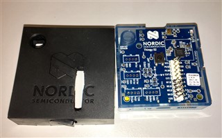
In order to use the MOSFETs on the Thingy:52, you have to solder on a pin header to the P4 solderpads on the PCB, see image below.
The following image shows the Thingy:52 with a 20-pin header soldered onto the P4 header. The 4 MOSFETs are also highlighted with a black marker.
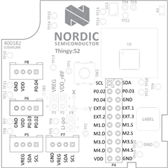
The P4 connector includes connections for Drain and Source of all 4 MOSFETs that we have available on the Thingy. The Gate of these MOSFETs are connected directly to the GPIOs on the nRF52832 SoC, see https://www.nordicsemi.com/DocLib/Content/User_Guides/thingy52/latest/UG/thingy52/hw_description/pin_maps, or table below. This means, if you set either of those GPIOs HIGH in the Thingy FW, it will "turn ON" the MOSFET and allow current to flow between Drain and Source.
| P0.18 | MOS_1 | Gate of N-MOS transistor externally available |
| P0.19 | MOS_2 | Gate of N-MOS transistor externally available |
| P0.20 | MOS_3 | Gate of N-MOS transistor externally available |
| P0.21 | MOS_4 | Gate of N-MOS transistor externally available |
LED with current limiting resistor
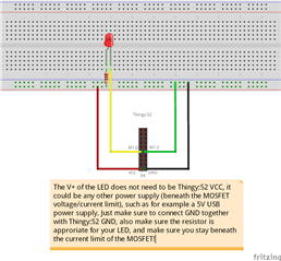
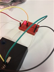
In order to test if this is working, I suggest connecting an LED through one of the MOSFETs. The connection would then be as following: VDD - Resistor - (+)LED(-) - MOS_1_D, MOS_1_S - GND. All of connections you need for a low current LED are available on the P4 connector. Please make sure that your resistor is appropriate for the LED you are trying to control so that you don't put too much current through it (I believe mine was rated at 20mA)! You should also make sure the power supply you are drawing power from is able to provide enough power for the LED to light up - if you are using the Thingy's VDD, you may want to limit the amount of current you draw from it! If any doubts, I suggest using an external 5V USB charger or something instead. Last thing to note: if you are using an external power supply, make sure you connect the GND of the Thingy with the GND of your power supply; otherwise it will not work properly. The following Fritzing diagram shows the setup I was using:
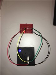
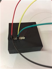
The following images shows the actual setup with the Thingy:52 I was using.
MOSFET DMN3190LDW Specifications
If you, like me, "always" forget how to read the specification of a MOSFET transistor between every time yo use one, let me guide you through this one for the ratings we need.
DISCLAIMER: It's been a while since I looked at transistor hardware datasheets, so anything I state in this section might be completely wrong and I encourage you to make sure the information is accurate. However, I did get my LED strips lit up, so I believe some of my statements should be correct..
First thing first, find the datasheet of the MOSFET (I have provided a link above). The DMN3190LDW is a dual N-channel enhancement mode MOSFET, which means there are two MOSFETs in this IC. The IC also contains a diode and zener diode for protection, but I won't be explaining those.
The maximum ratings of the MOSFETs inside the IC can be found in the "Maximum Ratings" table, duh..:P One of the things we would like to know is the MAX voltage we can pass through the MOSFET for the item we are controlling without damaging the MOSFET. This is the Max Drain-Source Voltage, V_DSS. This has a maximum value of 30V as you can see in the datasheet. Given this, we know that a 5V or 12V power supply will be fine to use. We can also use VDD of the Thingy, which is 3.3V.
Another max rating we would like to know if the maximum amount of current we can pass through Drain-Source, I_D. The Maximum Ratings table might in this case be a bit misleading because the Max Continuous Drain Current it provides is given a specific GATE voltage, V_GS of 10V. On the Thingy, the GATE voltage will be 3.3V, and not 10V - so the max drain current this table gives us is useless except to give us an upper limit to I_D. To find the max drain current we can pass through the MOSFET, we can use one out of two particular Figures in the datasheet. One figure usually shows the relationship between I_D and V_DS (Drain-Source Voltage, not V_DSS which is the max V_DS), and we can use this figure in combination with our Gate voltage and the voltage we intend on passing through Drain-Source, to find out Max I_D. In "Figure 1 - Typical Output Characteristic", we can see that with a GATE voltage (V_GS) of 3.0V, if we pass 5V through Drain-Source (V_DS), we will get a maximum drain current (I_D) slightly above 0.4A. If V_GS is 3.5V (the curve above the 3.0V curve), we see that max I_D at the same V_DS increases to almost 1.4A. The VDD of the Thingy is 3.3V and this will be the GATE voltage of the MOSFET. This means that the curve we were looking for is not plotted into the Figure, but we can easily estimate this in between the other two. So with V_GS at 3.3V, V_DS at Thingy VDD which is the same, 3.3V; we will get a max I_D above 0.4A, and below ~1.3A. So lets assume we get a max drain current I_D of 0.9A. As long as we stay below this we should be fine. If you are using 5V power supply instead of Thingy VDD, you will get a even higher I_D.
Another common thing to look for in a MOSFET datasheet would be the Gate Threshold Voltage (V_GS(th)). This is the Threshold voltage required to turn the MOSFET ON - ie. you need at least this amount of voltage at the Gate before current will flow through Drain-Source. For this MOSFET, the threshold is between 1.5V and 2.8V (varying between ICs), so the VDD of our Thingy at 3.3V is sufficient to turn if ON. This is already routed on the Thingy HW, so there isn't anything we can change here, but it's nice to at least understand how it works.
Switching MOSFET from nRF Connect
Download nRF Connect for iOS/Android
To turn the MOSFETs on/off, we will first be using the nRF Connect phone application, https://www.nordicsemi.com/Software-and-Tools/Development-Tools/nRF-Connect-for-mobile. If you have not done so already, please install it.
Connect to Thingy:52
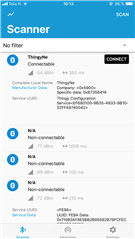
The Thingy:52 will be advertising as "Thingy", or the name you have set it to.
- Click "Connect" to connect to the device.
Find the appropriate BLE Service
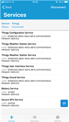
Once you are connected, you should see the different services that are present on your device. Please review the Thingy FW documentation: https://nordicsemiconductor.github.io/Nordic-Thingy52-FW/documentation/index.html, if you have any doubts about which services are present and what each service provides. The service we will be using to control the MOSFETs on the Thingy is the User Interface Service: https://nordicsemiconductor.github.io/Nordic-Thingy52-FW/documentation/firmware_architecture.html#arch_user_interface, with its Characteristic "EXT pin characteristic". In the Thingy App on your phone;
- Click the "Thingy User Interface Service"
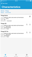
Using the EXT Pin Characteristic
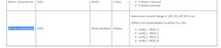
You should now see the Characteristics "Thingy Button", "Thingy LED", and "Thingy EXT Pin". The EXT Pin characteristic is used to control all the MOSFETs on the device. From the FW documentation, the EXT Pin characteristic accepts the inputs 0x0 or 0xFF (255). 0 is off, 255 is on. PWM is not currently implemented in the Thingy FW as you can see from the following source (as of v2.1.0): https://github.com/NordicSemiconductor/Nordic-Thingy52-FW/blob/99be6c170612faad070c02e857de27687480a03f/source/modules/m_ui.c#L274. The characteristic consists of 4 bytes (4 uint8_t's). Byte 1 controls MOS_1, byte 2 controls MOS_2, byte 3 controls MOS_3, and byte 4 controls MOS_4. Which means, in order to turn all of the MOSFETs "on", we write the value 0xFFFFFFFF to this characteristic. In order to turn all of the MOSFETs "off", we write the value 0x00000000.
![]()
Turn ON MOS_1 and MOS_2, Turn OFF MOS_3, and MOS_4
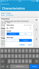
Turn MOSFET 1 and 2 on, while keeping MOSFET 3 and 4 off;
- Click the "bar + arrow UP" button on the "Thingy EXT Pin" characteristic
- Set write value to be: ffff0000
- Leave "Format" set to "Byte Array" and "Write type set to "Request"
- Click "SEND"
MOS_1 and MOS_2 will now be turned ON, and if you connected an LED through MOS_1 like I explained earlier in this blog post, this LED should now be emitting light. If you have connected an LED to MOS_2 it will do the same. If you have connected anything to MOS_3 and MOS_4, these should not have changed.
NOTE: If you are using an external power supply and your LED (strip?) does not light up, please make sure GND of your power supply is connected to GND of the Thingy. This is important because the GATE "signal" of the MOSFET, which is connected to the Thingy (P0.18 for MOS_1), is referenced to the SOURCE, which is probably connected to GND of your power supply. Which means that GND of the Thingy needs to match GND of your power supply.
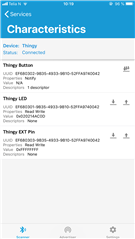
Read back the value you just wrote
To see which value that was written to the EXT Pin characteristic earlier (/to read the state of the MOSFETs);
- Click the "bar + arrow DOWN" button on the "Thingy EXT Pin" characteristic
The "Value" of the characteristic should now have been updated to match the current value of the MOSFETs. Earlier we wrote it to be 0xffff0000, Value should now show precisely this.
Turn OFF all MOSFETs
- Click the "bar + arrow UP" button on the "Thingy EXT Pin" characteristic
- Set write value to be: 00000000
- Leave "Format" set to "Byte Array" and "Write type set to "Request"
- Click "SEND"
All MOSFETs will now be turn OFF, and the LED should now also be OFF.
Controlling LED Strips through the Raspberry Pi
If you are interested in for example controlled some LED strips using a Raspberry Pi, the Raspberry Pi can interface with the EXT Pin characteristic using the Python Bluepy library. Please see https://devzone.nordicsemi.com/b/blog/posts/nordic-thingy52-raspberry-pi-python-interface for more information on using the Bluepy library to interface the Thingy:52 from a Raspberry Pi.
Reference
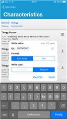
The following images should show what to expect when using the nRF Connect Phone application. The only difference from the sequence described above is that the value 0xffffffff was used instead of 0xffff0000. As mentioned, 0xFFFF FFFF turns all MOSFETs ON, while 0xFFFF 0000 only turns on MOS_1 and MOS_2.
Connecting to the Thingy:
Finding the Thingy UI Service:
Finding the EXT Pin Characteristic:
Writing 0xFFFF FFFF:
Reading the value after setting it to 0xFFFF FFFF:
Writing 0x0000 0000:

-

aravindaru
-
Cancel
-
Vote Up
0
Vote Down
-
-
Sign in to reply
-
More
-
Cancel
Comment-

aravindaru
-
Cancel
-
Vote Up
0
Vote Down
-
-
Sign in to reply
-
More
-
Cancel
Children