
The nRF52840 Dongle is a superb companion for several nRF Connect for Desktop apps and is a good device for doing large scale mesh test setups and similar, with its low cost and small size. It can also be used for development, and easily programmed over USB DFU from nRF Connect Programmer. The lack of an onboard debugger means that common debugging techniques such as stepping through code or accessing registers are not possible unless you connect an external debugger. The nRF52840 DK is a better choice for a stand-alone development platform.
This tutorial demonstrates how to adapt and program nRF5 SDK example applications to the nRF52840 dongle using USB DFU. It also describes how to program the dongle via Serial Wire Debug (SWD) using an external debugger (for instance a nRF52840 DK or nRF52 DK). Lastly, it will describe how you can recover if you have put the nRF52840 Dongle is in a non-programmable state.
Note: If you are using the nRF Connect SDK the instructions on how to adapt a nRF5 SDK project is not valid. Using the nRF Connect SDK the only adjustment you need to do to build an existing sample for the nRF52840 dongle is to specify that the board is nrf52840dongle_nrf52840.
USB bootloader and MBR
The nRF52840 Dongle is shipped with an Open USB bootloader which allows it to be programmed without the need for a debugger. You do not need to understand the bootloader in order to use it, as most of the DFU related stuff is typically handled by the nRF Connect Programmer app. However, an application developer must be aware of the existence of the bootloader and adjust the memory layout of the application accordingly.
The USB DFU system consists of the following parts:
- The Master Boot Record (MBR)
- The Open USB bootloader
- The DFU Trigger Library (optionally part of the application)
The MBR occupies the first flash page (address 0 - 0xFFF) and also reserves the lowest 8 bytes of RAM (0x20000000 - 0x20000007) for interrupt forwarding. The MBRs primary responsibility is to support safe upgrades of the bootloader. The MBR itself is never updated.
The bootloader is responsible for programming an application or SoftDevice via USB. The USB bootloader starts at address 0x000E0000 and occupies the rest of the flash (this includes the Bootloader settings page and MBR parameter storage page). See Memory layout for details.
The DFU Trigger library can be included in an application to allow the USB host to put the nRF52840 Dongle in DFU mode. This is for instance used in the Connectivity firmware that is used by the nRF Connect BLE app. Most SDK example applications do not include this library, and in that case, the dongle must be put in DFU mode by pressing the RESET button.
Adapting nRF5 SDK projects for the nRF52840 Dongle
Most SDK example application can be used with the nRF52840 dongle with a few adjustments. The application must be built so that the flash (ROM) and RAM memory layout does not conflict with the MBR and bootloader.
The SDK examples use the Board Support Package (BSP) to abstract away differences between different boards. Note that examples that rely on more buttons or LEDs will need more adjustments to work with the nRF52840 Dongle.
Most example projects use UART and/or RTT logging by default, neither which can be used with the dongle without additional hardware. Depending on the configuration this may cause problems so it is a good idea to disable logging by setting NRF_LOG_ENABLED to 0 in sdk_config.h
Adapt a simple example (without SoftDevice)
In this example, we will adapt the Blinky Example for the nRF52840 DK for the nRF52840 Dongle. The SDK already has dongle projects for the Blinky example which can be used as a reference. The instructions are for Segger Embedded Studio, but this approach can easily be adapted to any other toolchain or SDK example without SoftDevice. Remember to select the Common configuration in the upper left corner of the Options window when editing Segger Embedded Studio configurations.
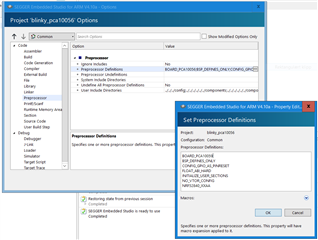
Step 1: Update the Preprocessor Definitions by removing BOARD_PCA10056 and inserting BOARD_PCA10059:
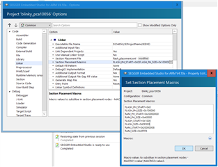
Step 2: Adjust the linker configuration. Set FLASH_START=0x1000 to place the application right above the MBR. You should also set FLASH_SIZE=0xDF000 to make sure that there is room for the bootloader at the end of the flash. Set RAM_START=0x20000008, as the first 8 bytes are used by the MBR for interrupt forwarding and adjust the size accordingly by setting RAM_SIZE=0x3FFF8.
Program application using nRF Connect Programmer
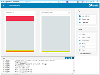
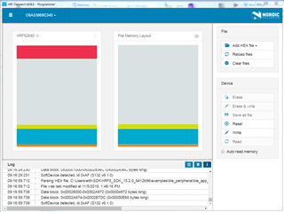
The simplest way to program the dongle is to use the nRF Connect for Desktop and launch the Programmer app:
- Open nRF Connect for Desktop and launch the Programmer app.
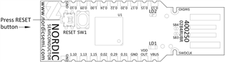
- Press the reset button to put the Dongle in DFU mode. This is not needed if the currently running application uses the DFU trigger library. Note that the reset button is the sideways button right next to the more obvious SW1 button on the Dongle:
- Select the dongle in the dropdown in the upper left corner if it is shown.
- Click "Add HEX file" to select the application hex file to program onto the dongle.
- Click "Write" to write the firmware to the dongle.
The device will reset when the upgrade completes and the dongle will no longer show up in nRF Connect unless the application used DFU Trigger Library is used, as it is no longer in DFU mode. You will get an error stating "Reopen device failed" in this case, and have to push the RESET button in order to make it show up in nRF Connect Programmer again.
Adapt a BLE example (with SoftDevice) and program it using nRF Connect Programmer
For BLE examples the SoftDevice and MBR is already present, so the only thing you need to do is to update the Preprocessor Definitions by removing BOARD_PCA10056 and inserting BOARD_PCA10059 in the same way as for the example without SoftDevice.
Program the application using nRF Connect in the same way as described for the previous example. You must add the SoftDevice hex in addition to the application hex file before you press "Write" in cases where the Dongle currently does not have any SoftDevice or if the SoftDevice version does not match the requirement of your application. You can also use a single hex file where the application and SoftDevice are merged.
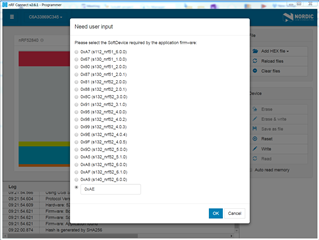
You can optionally program only the application if the current SoftDevice is already programmed to the board. In that case, you will be asked to specify the SoftDevice ID your application expects so that the bootloader can check this and reject the upgrade if it does not match. In case your SoftDevice version is not in the list, you should find the correct SoftDevice ID in the release notes of the SoftDevice and enter it in the text box.
Programming an example using nrfutil
Programming manually using nrfutil can be more time consuming and error prone than using the nRF Connect Programmer app, but it is useful in cases where you want to automate the programming process. In this example, we will continue with the BLE Blinky Application that you have already adapted and see how we can program it using nrfutil.
Step 1a: Either create an upgrade DFU zip package containing only the application:
nrfutil pkg generate --hw-version <HW VERSION> --debug-mode --sd-req <SOFTDEVICE ID> --application <APP HEX> <DFU ZIP>
Example:
nrfutil pkg generate --hw-version 52 --sd-req 0xAE --debug-mode --application ble_app_blinky_pca10059_s140.hex dfu.zip
Step 1b: Or create an upgrade DFU zip package containing both the application and SoftDevice:
nrfutil pkg generate --hw-version <HW VERSION> --debug-mode --sd-req 0x00 --sd-id <SOFTDEVICE ID> --application <APP HEX> --softdevice <SD HEX> <DFU ZIP>
Example:
nrfutil pkg generate --hw-version 52 --debug-mode --sd-req 0x00 --sd-id 0xAE --application ble_app_blinky_pca10059_s140.hex --softdevice s140_nrf52_6.1.0_softdevice.hex dfu.zip
Step 2: Program the zip package:
nrfutil dfu usb-serial -pkg <DFU ZIP> -p <VIRTUAL SERIAL PORT> -b 115200
Example:
nrfutil dfu usb-serial -pkg dfu.zip -p COM60 -b 115200
Using an external debugger
The nRF52840 Dongle can be programmed and debugged by connecting an external debugger.
A word of caution before you begin
The nRF52840 chip on the dongle hardware is configured in high voltage mode. This uses REG0 to lower the chip supply voltage (VDD), and the default value is 1.8 V, configured by the REGOUT0 register in UICR. This is too low to be used with the onboard programmer on the nRF52840 DK, so erasing or programming with a firmware that does not configure the regulator for a higher VDD will leave it in a state where it cannot be re-programmed from a DK.
To avoid problems if you are using a debugger without level shifter (such as a nRF52840 DK):
- Avoid erasing the UICR of the chip (i.e. do not do a full chip erase).
- If you must erase the UICR, make sure that you do not reset the board until after you have programmed either REGOUT0 directly or firmware that sets it.
- Alternatively, modify the dongle as explained under External regulated source and supply the dongle directly from the nRF52 DK (assuming it is used as a debugger).
Adapting firmware to set REGOUT0 properly
The firmware must set REGOUT0 to 3 V in order to allow it to be debugged from a DK. This is handled by the BSP if it is used with board correctly set to pca10059 by defining BOARD_PCA10059, and the firmware calls bsp_board_init().
If the BSP is not used, you should instead do the same thing directly by calling this code as early as possible in your firmware to set the REGOUT0 register if need:
if ((NRF_UICR->REGOUT0 & UICR_REGOUT0_VOUT_Msk) ==
    (UICR_REGOUT0_VOUT_DEFAULT << UICR_REGOUT0_VOUT_Pos))
{
    NRF_NVMC->CONFIG = NVMC_CONFIG_WEN_Wen;
    while (NRF_NVMC->READY == NVMC_READY_READY_Busy){}

    NRF_UICR->REGOUT0 = (NRF_UICR->REGOUT0 & ~((uint32_t)UICR_REGOUT0_VOUT_Msk)) |
                        (UICR_REGOUT0_VOUT_3V0 << UICR_REGOUT0_VOUT_Pos);

    NRF_NVMC->CONFIG = NVMC_CONFIG_WEN_Ren;
    while (NRF_NVMC->READY == NVMC_READY_READY_Busy){}

    // System reset is needed to update UICR registers.
    NVIC_SystemReset();
}
With this in place, you can connect the nRF52840 Dongle to the Debug out connector of a nRF52840 DK or use another debugger of your choice. The SWD interface documentation shows how you can access the SWD port. Another alternative is to simply solder SWDIO and SWDCLK wires directly to the two plated half-holes close to the "head" of the dongle. Now you can program the nRF52840 Dongle like you would any other nRF52840 Device with a debugger using, for instance, nrfjprog or the nRF Connect Programmer app.
Recover after an accidental UICR erase
You have two options for recovering when the REG0 (VDD) voltage is 1.8 V (typically after a UICR erase):
- Either use a debug probe that adapts the logic levels to the target device (for instance a J-Link PRO). Program firmware that configures REGOUT0 for 3 V.
- Or modify the dongle so that it can be supplied by an external supply and use the nRF52840 DK to program it.
- Adapt the dongle hardware as described under External regulated source in the nRF52840 Dongle documentation.
- Connect VDD from the nRF52840 DK to VDD OUT on the nRF52840 Dongle.
- Program via SWD as you have previously done (but remember to set REGOUT0 this time).
Revert to production bootloader
If you have erased the bootloader from SWD, it has to be programmed again before you can go back to programming the nRF52840 Dongle via USB DFU. Use the attached hex file (pca10059_bootloader.zip), which contains the MBR and Open bootloader with the correct public key. You can also use the Open bootloader example project from the SDK, but it does not include public key needed to update the bootloader itself over USB DFU.
Further Reading
P.S.: Please post any questions you might have on the forum and not as a comment below the tutorial. This makes it easier for other users and Nordic employees to see and search for your questions and you will most likely get a faster response.
Top Comments
-

brianreinhold
-
Cancel
-
Vote Up
0
Vote Down
-
-
More
-
Cancel
-

Einar Thorsrud
in reply to brianreinhold
-
Cancel
-
Vote Up
0
Vote Down
-
-
More
-
Cancel
-

brianreinhold
in reply to Einar Thorsrud
-
Cancel
-
Vote Up
0
Vote Down
-
-
More
-
Cancel
Comment-

brianreinhold
in reply to Einar Thorsrud
-
Cancel
-
Vote Up
0
Vote Down
-
-
More
-
Cancel
Children