Welcome to the online power profiler (OPP) for nRF91. Use this tool to estimate the current consumption of the nRF91 LTE modem. The OPP supports both NB-IoT (cat NB1) and LTE-M (cat M1), and several other network parameters.
When connected to an LTE network there are many parameters you are not able to control. Some parameters can be requested by the UE, but in the end it's the network that decides most of them. These parameters can have a significant impact on current consumption, and in order to get an idea of what to expect when you connect to the network in your area, you can use the OPP to match the network parameters, and then see the expected current consumption.
The OPP is based on measurements conducted on a nRF9160 DK while communicating with a CMW500 radio communication tester. It is meant for evaluation purposes only and will not give the exact numbers in every use case.
You can also check out this video showing how the Online Power Profiler can be used to estimate the power consumption in your application, comparing it with results from the PPK2:
Contents
Test setup
The current consumption is measured at 3.7V on VDD, and includes both the MCU and modem currents, as well as the SIM card.
The firmware used in the measurements is based on the serial LTE modem application which can be found here. The FW puts the MCU to sleep, and turns off the UART.
The hardware used is an nRF91 DK (PCA10090 v0.9.0) communicating with a CMW500 radio communication tester.
Supported parameters
General settings
- LTE category: Choose between LTE cat M1 or LTE cat NB1. Not all networks support both M1 and NB1.
- TX output power: The output power depends on the signal conditions, and is dynamically adjusted in real time by the network. You cannot set a fixed output power in the application. By changing the value in this field you will get an idea on how the output power will impact the current consumption in good versus bad signal conditions
PSM - Power Saving Mode
- TAU timer: Also know as T3412 timer or the PSM sleep interval. It specifies how often the UE is required to wake up from PSM to do a TAU (Tracking Area Update)
- Active timer: Also known as the T3324 timer. It defines the length the UE is required to stay in RRC idle mode before it can enter PSM. In RRC idle mode the UE is reachable by the network in case it needs to receive more data. This parameter can be requested by the UE, however the requested value might not be supported by the network.
RRC idle mode
- iDRX interval: This is the RX paging interval, i.e. how often the UE listens for incoming data on the network, in RRC idle mode. A longer interval means higher latency for the incoming data. This parameter can be requested by the UE, however the requested value might not be supported by the network.
RRC connected mode
- Data upload size: You can add data upload to the RRC connection event to get an idea of how much energy is needed to upload a specific payload. The data was collected by measuring a simple UDP upload to a server with different payloads.
- Data upload interval: Data upload frequency in number of TAU events. In case the application wants to transmit data it makes sense to do this while the UE wakes up from PSM to do the required TAU, in order to save power. As a consequence, and also to simplify this tool, the data upload interval is configured as a multiple of the TAU timer. This is not a limitation in the technology; you can wake up and attach to the network regardless of the specified TAU interval.
- cDRX interval: Similar to the iDRX interval, except that this is during the RRC connected mode. This is decided by the network, and cannot be requested by the UE
- RRC inactivity timer: Decides how long the UE is required to stay in RRC connected mode before it can enter RRC idle mode (eDRX idle) or PSM. This is to avoid having to set up a new RRC connection immediately if there is a pending ACK or more data to be received from the network. This is decided by the network, and cannot be requested by the UE
SIM card settings
- Clock stop current: Specified SIM card sleep/retention current at 1.8V
-
Enable power down: Depends on the SIM card specifications. Most SIM cards requires the sleep time to be above a certain value before it can be shut down completely, i.e. a minimum power down interval is specified by the SIM. This is to reduce the SIM card life time because of flash wear-out, since data to be retained has to be written to memory before power down. Newer SIM cards made for low power IoT applications support minimum power down intervals of 1 minute or less, while older SIM cards usually support intervals of 10 minutes or more. Some SIM cards can't be powered off at all
-
Minimum power down interval: The minimum power down interval supported by the SIM
CMW500 setup
A configuration file containing the parameters used by the CMW500 during testing is included here:
https://devzone.nordicsemi.com/cfs-file/__key/communityserver-wikis-components-files/00-00-00-00-01/DAU_2D00_NB1_2D00_M1.dfl
Peak currents
The tool does not show peak currents. The different bars in the graph show the average current within a specified event type, e.g. iDRX event. The radio RX/TX will typically give the highest peak currents, but it is only a small part of the event itself, hence the average current will be lower than the peak current.
Here is an example showing an cDRX paging event, and the corresponding result from the OPP.
Figure 1 shows a cDRX paging event. The average current, length and charge within the cursors are given in the OPP plot, as shown in figure 3. The maximum current (44,4 mA) is not included in the OPP plot.
Figure 2 shows the average current during the cDRX paging, the average current is given in the RRC connected mode table, as shown in figure 3.
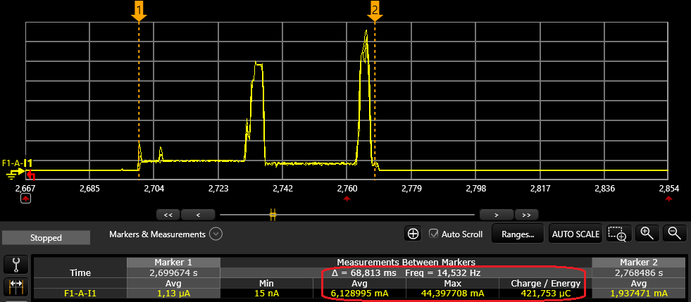
Figure 1: cDRX paging event
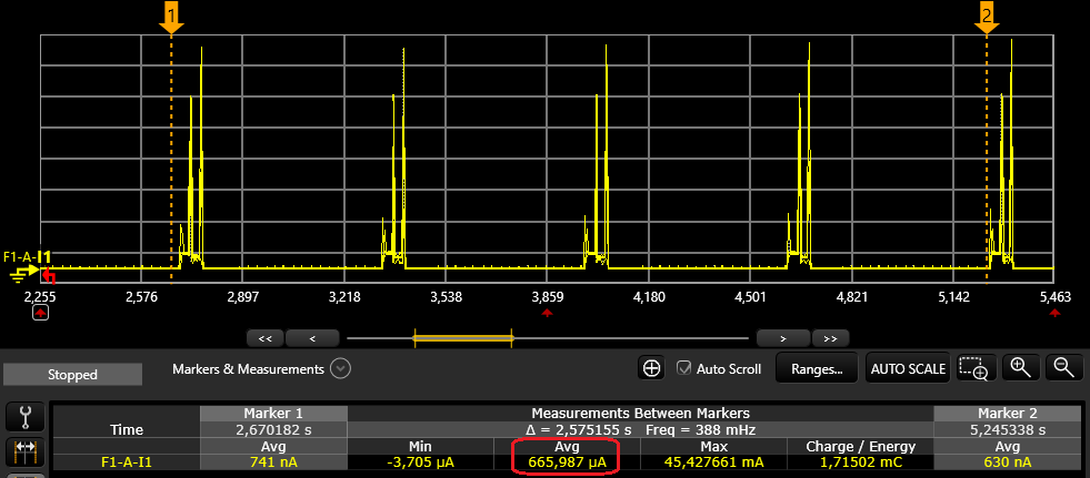
Figure 2: cDRX average current
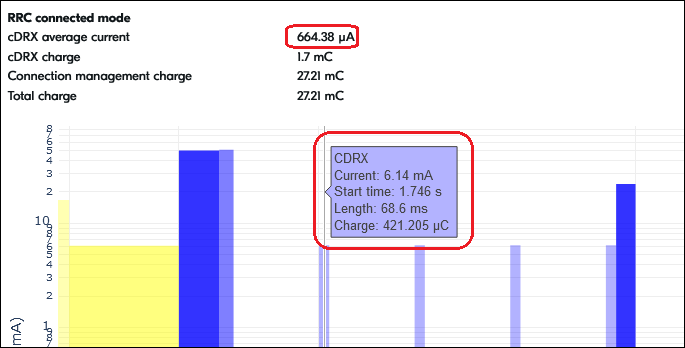
Figure 3: OPP showing cDRX numbers
Disclaimer
This tool is based on a model of measured values and is not showing the actual measurement. The result is therefore an estimate of the expected value.
The measurements which the model is based upon are conducted on a nRF9160 module while communicating with a CMW500 Radio Communication Tester. This controlled test environment represents in many cases ideal conditions which may not be reproducible in a real network. It does not consider poor signal conditions which would result in different CE levels and repetitions.
Further, different networks support different parameters which can affect the current consumption. This tool does not give the opportunity to change every possible network configuration parameter, thus in some cases the modeled values will deviate from what is seen in a real network.