This post is older than 2 years and might not be relevant anymore
More Info: Consider searching for newer posts

nRF52832 ANTENNA

Hi,

so i was using the NRF51822-QFAC with an external balun and this antenna chip 2450AT43A100E .

now i want to move to the nRF52832 chip and from what i read is that the balun is integrated into the chip which is a good news,

1/ i want to know if the antenna chip 2450AT43A100E still OK for the nRF52832 ? knowing that i want to take advantage of the extra range proposed by the BLUETOOTH 5?

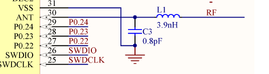
2/ according to the Schematic QFAA QFN48 section inside the datasheet the inductance L1 and the capacitor C3 connected to the ANT output are they the antenna tuning component or are they a simple component that i have to put them there by default?

image description

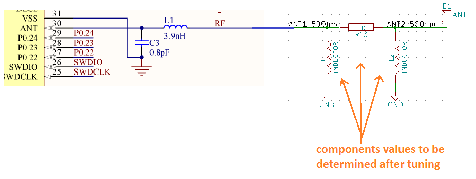
in case they're not the antenna tuning components should my schema look like the image below ? :

image description

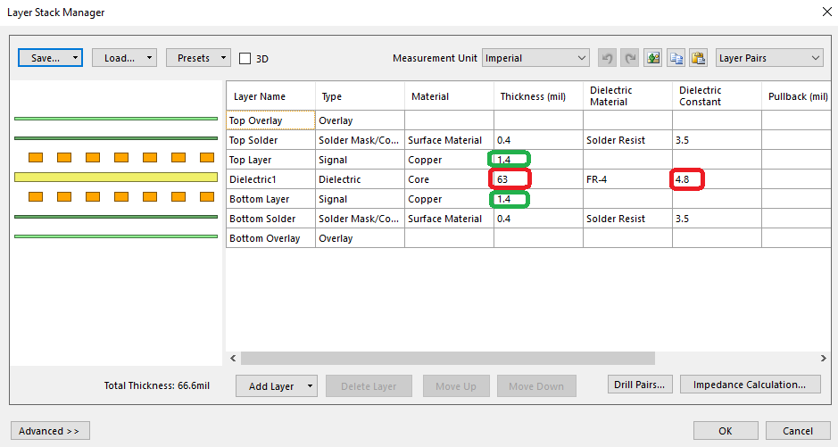
3/ i downloaded the nRF52832-QFAx Reference Layout 1_1 and opened the nRF52832-QFAA project with altuim software. and i want it to check how the antenna track was made and calculate its impedance.

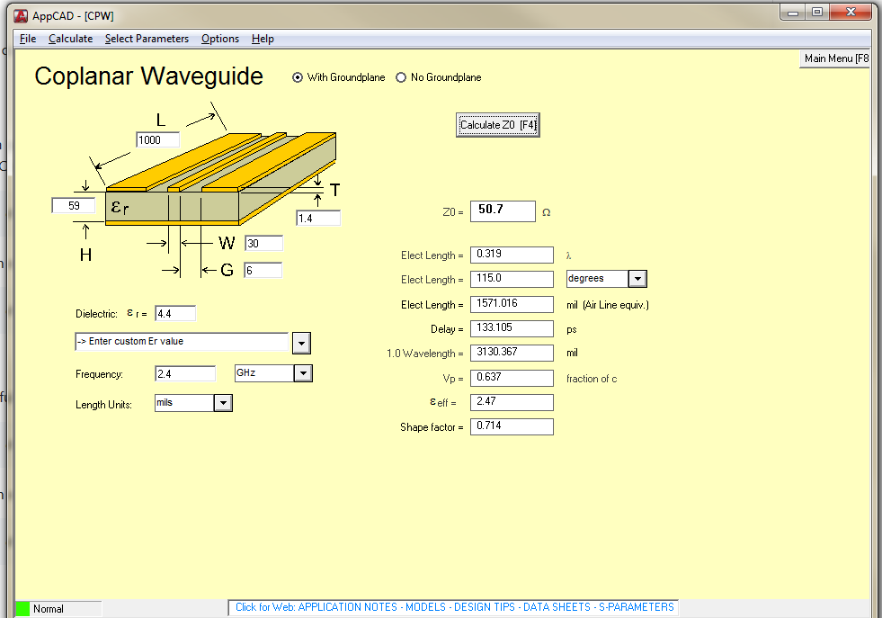
above a screen shot of the values that i got inside altuim :

image description

image description

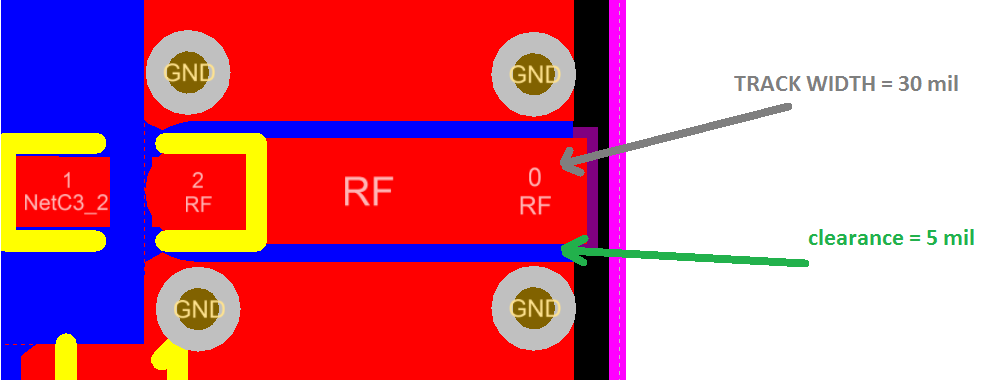
when i tried to calculate the antenna track impedance using theses values i figure out that the track impedance is equal to 46.2851 Ohm and not 50 Ohm ?

below a screen shot of the calculation :

image description

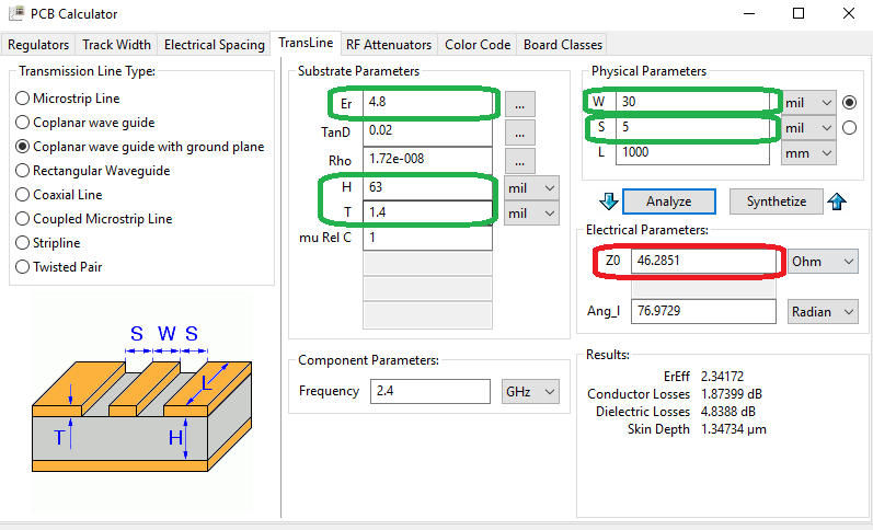
i even used other online tools to calculate the impedance and had the same result

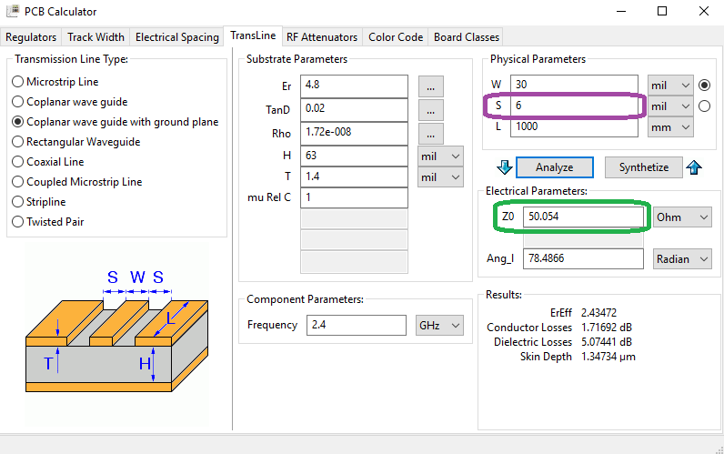
the only way to get 50 Ohm is to change the clearance to 6 mil,

image description

did i do something wrong? any explanation ?

  • Hello Tizana

    1 – The nRF52832 does not support the Long Range part of Bluetooth 5, only the 2Mb/s PHY. For Long Range you will need to use the nRF52840. As for the antenna it should work fine with Long Range as it has a maximum input power of 2W, while the nRF52840, which has a higher output power than any of our previous products, has a maximum output power of 8dBm (6.3 mW)

    2 – The output impedance of the chip is not 50 Ohm. L1 and C3 are there to match it to 50 Ohm, and suppress harmonics. For them to provide a proper match, it is important the layout surrounding them are as close to the reference design as possible.

    As you're using a chip antenna a PI network, as shown in your figure, may be necessary to properly tune the antenna to 50 Ohm.

    In regards of layout for the nRF52 I recommend this blogpost.

    3 – I see the reference design has listed 4.8 as its dielectric constant. This is quite likely too high as the dielectric constant will become lower as the frequency goes higher. The development kit uses 4,4 which I believe to be more correct. The design there gives a bit more accurate result, closer to 50 Ohm. I will look further into the exact numbers of the reference layout.

    The exact dielectric constant of the substrate you use will differ based on who produced it. For a more accurate number you will either have to make measurements yourself, or contact the company who made your substrate.

    That being said a mismatch of 5 Ohm is not bad giving a reflection coefficient just above 4,5% if the antenna is perfectly matched to 50. The trace in the reference layout is 2,4 mm long (94,5 mil) which corresponds to about 3% of the wavelength. This is not enough to have any significant impact on the impedance.

    Best regards

    Jørn Frøysa

  • thx for the answer, so no need for me to move from the NRF51822 to the nRF52832 , because my only goal was to improve the range, and the nRF52840 only available later in Q4 2017 ? right ?

  • As Jorn mentioned below, Er for standard RoHS FR4 (Tg 170c) generally has a dielectric constant of 4.2 to 4.4. The reality is unless you make that part of your spec the board vendor will not guarantee consistent 50ohm performance. In a spec'd 50ohm situation you tell them which artwork should be 50ohm and they control the board thickness and amount of epoxy vs. glass to get the solution to 50ohm. However, for your purposes don't worry about it. Anything 45 to 55 ohms will be fine. In your calculations you forgot to subtract 2xT from your H value. H is between the outer copper sheets. The outside is 0.062 so H is .062 - .0028 or 0.0592.

  • I disagree with Jorn though on the significance of 2 mm change in electrical length. On a board the wave travels at less than the speed of light due to Er. In this case about 64% of the speed of light. At 2.4GHz every 1.2mm of distance is 10 degrees of rotation around the smith chart. On a smith chart every 360 degree rotation corresponds to half a wavelength. If all these things were 50ohm they would just spin around the center of the smith chart. However, they are not and 10 or 20 degrees will change things considerably.
    When you finally do your antenna match just make sure it is conjugate to the nRF (as it appears on your board) and make sure to do the match while it is in any enclosure you are planning. Any plastic, metal or skin if it is worn nearby will change the antenna match.

  • By the way here is your design info with all the correct constants applied. Looks like you got it spot on!

    image description

Related