This post is older than 2 years and might not be relevant anymore
More Info: Consider searching for newer posts

Antenna tuning with chipset antenna

Hello,

I developed a Nordic board with 2450AT18B100 chipset antenna. I follow the design of Solar Powered Sensor Beacon.

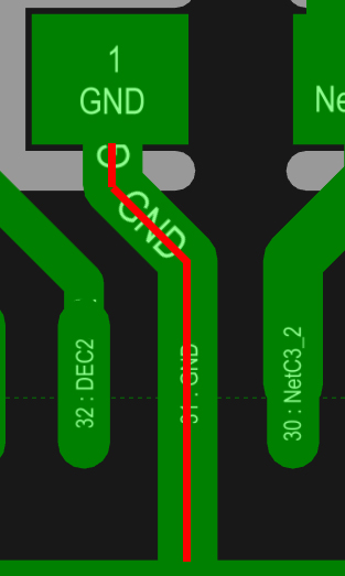
infocenter.nordicsemi.com/index.jsp I test it and it works fine, but I want to tuning the antenna in order to get minimum return lose in signal.

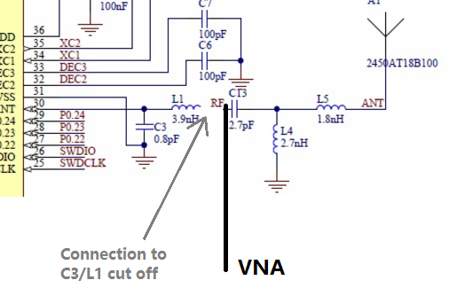
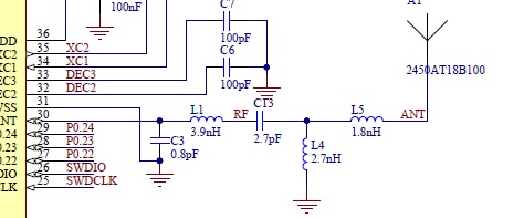
So, I implement this antenna circuit in my board. And

From johanson technology values are: I

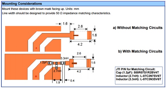
I suppose that from C3 and L1 you have to modify some references values of johanson chip antenna.

In general, my questions are:

Can you explain me each part of this circuit?.

Can you explain me why do you change this values and how do you calculated?.

Can you explain me how tuning the antenna?. Because your reference document for that do not explain how to do it in this case.

infocenter.nordicsemi.com/.../nwp_017.pdf

Thanks in advance.

Jose.

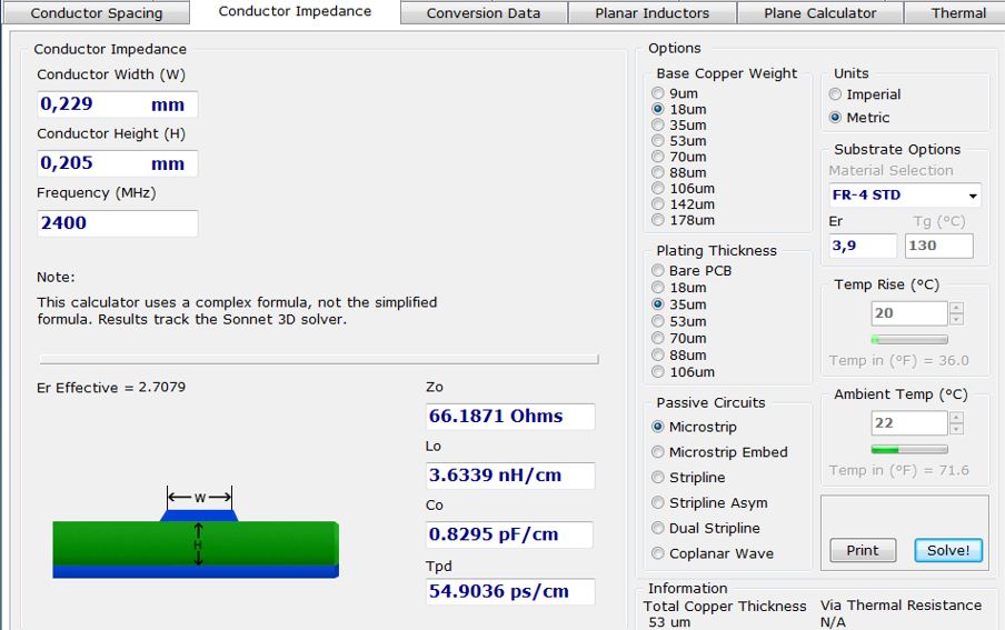
Others attached files. Conductor Impedance

image description

Trace Lenght Solar Beacon

image description

  • FormerMember
    0 FormerMember

    Impedance/output power of the chip: There are two ways to verify that the impedance is approximately 50 Ohm:

    Measure output power: If you have followed (copied) the reference layout, it should normally not be necessary to modify the values of C3 and L1. You can verify that the impedance is correct (50 Ohm) by measuring the output power using a spectrum analyzer. If the measured output power is the same as what it was set to be, the impedance is 50 Ohm.

    NB: Remember to measure the signal level of the harmonics and the frequency of 2xRX LO (center frequency 4.88 GHz) as well.

    Measure the impedance: A vector network analyzer (VNA) can be used to measure the impedance of the chip. Connect the VNA "to the chip" after C3 and L1, set the radio in nRF52832 in RX or TX mode, and measure the impedance. The impedance should be approximately 50 Ohm.

    Tuning of the antenna: To tune the antenna, a VNA should be connected to the antenna, by connecting it right before the matching network, the order will be the following: VNA connected - matching network - antenna. The connection towards C3/L1 should be cut of, see picture below.

    image description

    When the VNA is connected, you should change the values in the matching network until the measured impedance is as close to 50 Ohm as possible across the band. Use the smith chart to get an approximation of the values for the matching network. Start with the components closest to the antenna.

    Typically, chip antennas are quite narrow banded. We usually say that if the measured SWR is below 2 across the band, the antenna is well tuned.

    As initial values, when doing the tuning, I would recommend the following: C13 and L5 is 0 Ohm, and L4 is not mounted.

  • Hello Kristin,

    Thanks a lot for your swift reply. I have a new questions...

    How can I measure the output power?.

    About VNA I suppose that the signal of VNA is in C13 and the GND of VNA in L4 (GND), that is right?. About this process...that means that doing that we will be sure about the impedance adaptation between all parts but...what about the frequency resonance?. Imagin that impedance is right but frequency resonance is wrong... I suppose that you make some calculations to do that. Can you shared with us this calculations.

    Thanks in advance.

    Jose.

  • FormerMember
    0 FormerMember in reply to vidal

    I have updated my answer.

    The output power can be measured using a spectrum analyzer. It is also possible to use a VNA to measure the impedance of the chip, see the updated answer.

    Tuning of antenna: When connecting the VNA, the center "cable" should be connected to the C13, and the outer "cable" should be connected to ground (ground plane) close to where the center cable is connected.

    What do you mean by frequency resonance?

  • Dear Kristin,

    Thanks for your swift reply. Now I understand a little bit more. I am only have some questions:

    First at all, I have a VNA from 1MHz to 3GHz and a spectrum analyzer (MDO4034C + SA3) of 3GHz, so it is impossible to me measure at the harmonic at 4.88 GHz...Is this a great problem?. Why is not possible the measure the principal frequency (2.44GHz)?.

    Second, when you are referring to measure the output power, I suppose that is about to validate if I set TXPower register (0x50C) of nRF52 to 0x00 (0dBm) I see in the spectrum analyzer 0dBm. To do that I suppose that nRF52 have an special configuration in order to test it...similar to TX in continuous mode?.

    Thanks in advance.

    Jose.

  • Please,

    Can you answer my doubts?.

    Thanks in advance.

    Jose.

Related