This post is older than 2 years and might not be relevant anymore
More Info: Consider searching for newer posts

Antenna tuning with chipset antenna

Hello,

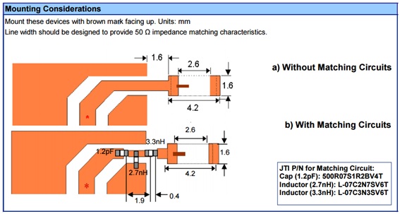
I developed a Nordic board with 2450AT18B100 chipset antenna. I follow the design of Solar Powered Sensor Beacon.

infocenter.nordicsemi.com/index.jsp I test it and it works fine, but I want to tuning the antenna in order to get minimum return lose in signal.

So, I implement this antenna circuit in my board. And
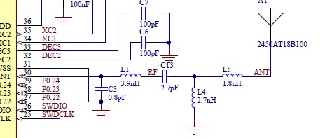
From johanson technology values are: I

I suppose that from C3 and L1 you have to modify some references values of johanson chip antenna.

In general, my questions are:

Can you explain me each part of this circuit?.

Can you explain me why do you change this values and how do you calculated?.

Can you explain me how tuning the antenna?. Because your reference document for that do not explain how to do it in this case.

infocenter.nordicsemi.com/.../nwp_017.pdf

Thanks in advance.

Jose.

Others attached files. Conductor Impedance

image description

Trace Lenght Solar Beacon

image description

  • FormerMember
    0 FormerMember in reply to vidal

    Measuring the harmonics: Yes, to measure the harmonics a spectrum analyzer for higher frequencies are needed. If you have copied our reference layout for L1 and C3, with the same component values and distances as in the reference layout, the harmonics will normally not create any problems. The reason why it is necessary to measure the harmonics is to pass the various regulatory standards. All regulatory standards have a maximum limit for signals that are out-of-band.

    Output power: You can use the "radio_test" example in the SDK to easily set the radio in continuous transmission with the desired output power.

  • Hello Kristin,

    Thanks for your reply. I only have two questions more and I will do some test.

    As you say I do not have tools to measure the second harmonic so I have to measure the impedance of the chip instead of output power. To do that I have to cut off the track in the same way of tuning antenna process?. I have to program nRF52 with radio_test" example (which configuration of the app)?.

    Best regards.

    Jose.

  • FormerMember
    0 FormerMember in reply to vidal

    Measuring the impedance of the ANT pin on the chip is an alternative way to verify that the output power from the chip is what it should be: When the impedance is (approximately) 50 Ohm across the band, the output power in the 50 Ohm reference point will be the same as what it was set to be. However, measuring the impedance does not, unfortunately, replace the measurement of harmonics. The only way to measure the harmonics is to use a spectrum analyzer. This .pdf explains an important aspect of C3/L1 in terms of suppressing harmonics.

    When using the radio_test example and you want to measure the output power, the signal should be unmodulated. Unmodulated signal is the default. In addition, you would need to set the following settings:

    Constant channel (TX): a, p, c

    Sweep (TX): a, b, p, t

  • Hello Kristin, Right now I can not do it, so I will try to measure the impedance with VNA. To do that I have to cut off the track in the same way of tuning antenna process????.

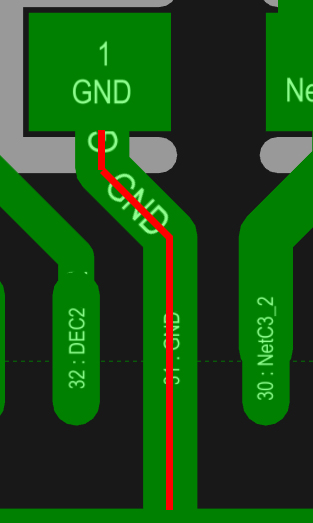
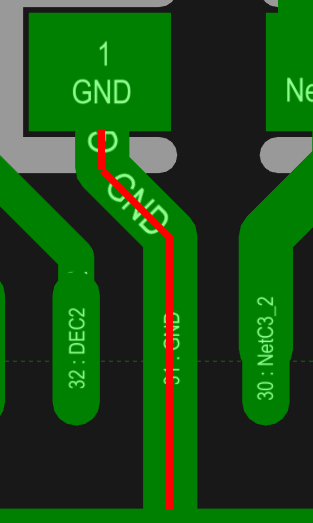
    Also I was doing some math. According to “nRF52 matching network.pdf” document shown that trace has 10nH/cm and I did some simulation and that trace has around 4nH/cm there are a lot of difference… do you know why???. Conductor Width is 9 mils. image description Also I was checking the distance. In Solar Beacon board, the distance is 1.694mm and in “nRF52 matching network.pdf” document is 0.9mm, do you know why???. I suppose that you are taking other reference. You can see in the picture below my reference of 1.694mm because I think that GND is the thermal/ground PAD of the nRF52.

    image description

    Thanks.

Related