This post is older than 2 years and might not be relevant anymore
More Info: Consider searching for newer posts

I have tried to produce a PWM signal of 33.33KHz at a GPIO pin of nRF52832!The duty cycle of the signal varies bizzaredly even after setting it to 50%!Can anyone help me out! I wanna run an external IC on this clock!Please find the screenshot attached!

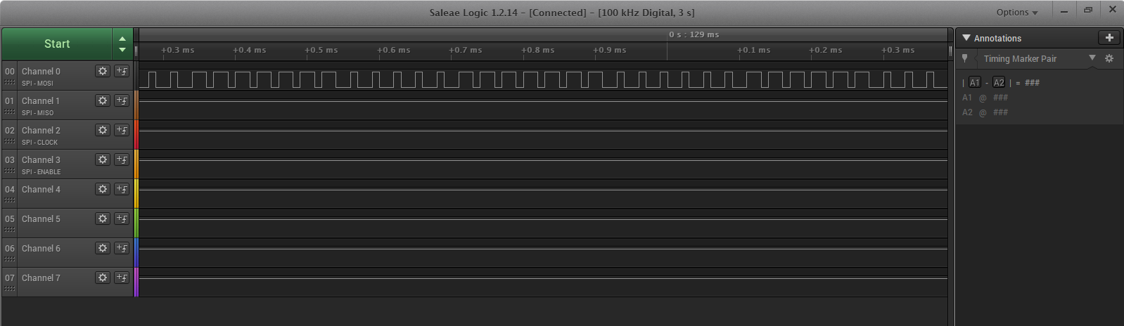
PWM.PNGHere is my code:

#include "nrf.h"
#include "nrf_gpio.h"
#include "nrf_drv_rtc.h"
#include "nrf_drv_clock.h"
#include "boards.h"
#include "app_error.h"
#include <stdint.h>
#include <stdbool.h>

#define COMPARE_COUNTERTIME  (3UL)                                       < Get Compare event COMPARE_TIME seconds after the counter starts from 0.

#ifdef  BSP_LED_0
    #define TICK_EVENT_OUTPUT    BSP_LED_0                        < Pin number for indicating tick event. 
#endif
#ifndef TICK_EVENT_OUTPUT
    #error "Please indicate output pin"
#endif
#ifdef BSP_LED_1
    #define COMPARE_EVENT_OUTPUT   BSP_LED_1                               < Pin number for indicating compare event.
#endif
#ifndef COMPARE_EVENT_OUTPUT
    #error "Please indicate output pin"
#endif

const nrf_drv_rtc_t rtc = NRF_DRV_RTC_INSTANCE(0); //< Declaring an instance of nrf_drv_rtc for RTC0. 

/** @brief: Function for handling the RTC0 interrupts.
 * Triggered on TICK and COMPARE0 match.
 */
static void rtc_handler(nrf_drv_rtc_int_type_t int_type)
{    nrf_gpio_pin_toggle(10);
    if (int_type == NRF_DRV_RTC_INT_COMPARE0)
    {
        nrf_gpio_pin_toggle(COMPARE_EVENT_OUTPUT);
    }
    else if (int_type == NRF_DRV_RTC_INT_TICK)
    {
        nrf_gpio_pin_toggle(17);
    }
}

/** @brief Function configuring gpio for pin toggling.
 */
static void leds_config(void)
{
    bsp_board_leds_init();
}

/** @brief Function starting the internal LFCLK XTAL oscillator.
 */
static void lfclk_config(void)
{
    ret_code_t err_code = nrf_drv_clock_init();
    APP_ERROR_CHECK(err_code);

    nrf_drv_clock_lfclk_request(NULL);
}

/** @brief Function initialization and configuration of RTC driver instance.
 */
static void rtc_config(void)
{
    uint32_t err_code;

    //Initialize RTC instance
    nrf_drv_rtc_config_t config = NRF_DRV_RTC_DEFAULT_CONFIG;
    config.prescaler =0;
    err_code = nrf_drv_rtc_init(&rtc, &config, rtc_handler);
    APP_ERROR_CHECK(err_code);

    //Enable tick event & interrupt
    nrf_drv_rtc_tick_enable(&rtc,true);

    //Set compare channel to trigger interrupt after COMPARE_COUNTERTIME seconds
    err_code = nrf_drv_rtc_cc_set(&rtc,0,COMPARE_COUNTERTIME * 8,true);
    APP_ERROR_CHECK(err_code);

    //Power on RTC instance
    nrf_drv_rtc_enable(&rtc);
}

/**
 * @brief Function for application main entry.
 */
int main(void)
{
    leds_config();

    lfclk_config();

    rtc_config();

    while (true)
    {
        __SEV();
        __WFE();
        __WFE();
    }
}
  • Hi,

    I recommend that you use the PWM peripheral for this.

    The code below will give you a 33.33 KHz clock at 50 % duty at pin 4.

    #include <stdio.h>
    #include <string.h>
    #include "nrf_drv_pwm.h"
    #include "app_util_platform.h"
    #include "app_error.h"
    #include "boards.h"
    #include "bsp.h"
    #include "nrf_drv_clock.h"
    #include "nrf_delay.h"
    
    
    #define OUTPUT_PIN 4
    
    static nrf_drv_pwm_t m_pwm0 = NRF_DRV_PWM_INSTANCE(0);
    
    // Declare variables holding PWM sequence values. In this example only one channel is used 
    nrf_pwm_values_individual_t seq_values[] = {0, 0, 0, 0};
    nrf_pwm_sequence_t const seq =
    {
        .values.p_individual = seq_values,
        .length          = NRF_PWM_VALUES_LENGTH(seq_values),
        .repeats         = 0,
        .end_delay       = 0
    };
    
    
    static void pwm_init(void)
    {
        nrf_drv_pwm_config_t const config0 =
        {
            .output_pins =
            {
                OUTPUT_PIN, // channel 0
                NRF_DRV_PWM_PIN_NOT_USED,             // channel 1
                NRF_DRV_PWM_PIN_NOT_USED,             // channel 2
                NRF_DRV_PWM_PIN_NOT_USED,             // channel 3
            },
            .irq_priority = APP_IRQ_PRIORITY_LOWEST,
            .base_clock   = NRF_PWM_CLK_1MHz,
            .count_mode   = NRF_PWM_MODE_UP,
            .top_value    = 30,
            
            //F(pwm) = F(clk)/top_value
            
            
            .load_mode    = NRF_PWM_LOAD_INDIVIDUAL,
            .step_mode    = NRF_PWM_STEP_AUTO
        };
        // Init PWM without error handler
        APP_ERROR_CHECK(nrf_drv_pwm_init(&m_pwm0, &config0, NULL));
        
        seq_values->channel_0 = 15;
        nrf_drv_pwm_simple_playback(&m_pwm0, &seq, 1, NRF_DRV_PWM_FLAG_LOOP);
        
    }
    
    
    int main(void)
    {
    
        // Start clock for accurate frequencies
        NRF_CLOCK->TASKS_HFCLKSTART = 1; 
        // Wait for clock to start
        while(NRF_CLOCK->EVENTS_HFCLKSTARTED == 0) ;
        
        pwm_init();
    
        for (;;)
        {
            
        }
    }
    
  • Hey ! Thanks for your support! But i'm getting a compile error saying "nrf_drv_pwm.h" file as not found! May i know how to fix this?

  • Are you using Keil? Then you need to add the driver to the project, and add the path to the "Include paths".

    But, e.g. the pwm_driver example should already have all the included paths and files added. The pwm_driver example is located in the folder <SDK_InstallFolder>\examples\peripheral\pwm_driver. Just remove everything in main.c, and add the code I posted instead.

  • No, I'm not using Kiel . I'm using windows command prompt! I have got the code running by changing makefile! adding nrf_drv_pwm.h files etc..But the code doesn't give a 50% duty cycle signal!

  • What duty cycle are you measuring? What SDK version are you using? Is this a nRF52-DK or a custom board?

Related