This post is older than 2 years and might not be relevant anymore
More Info: Consider searching for newer posts

Spectrum measurements with DTM firmware

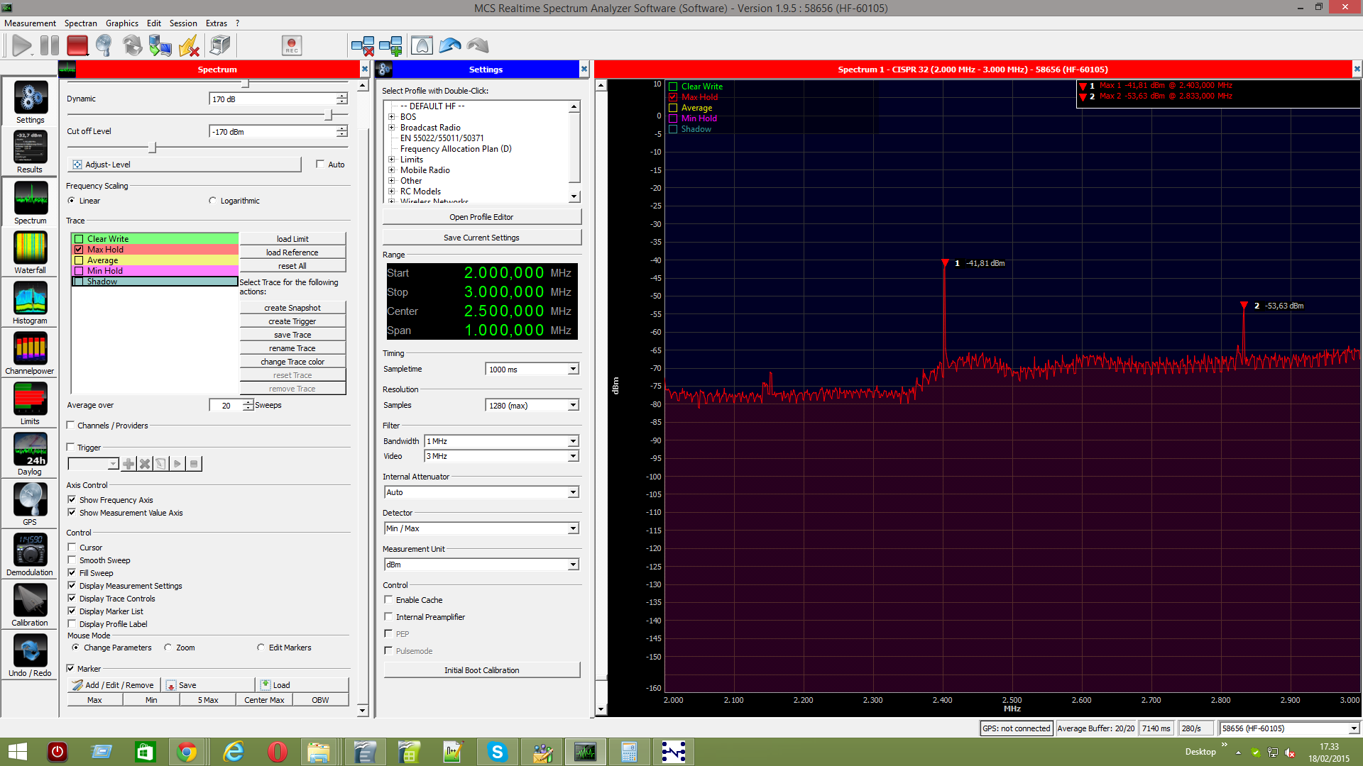
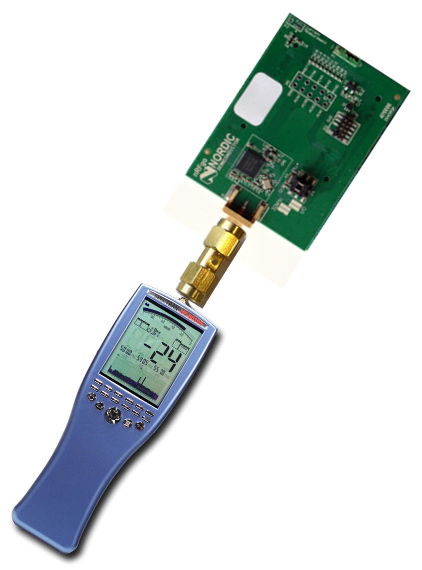
Hi all, we are performing some transmitter spectrum measurements using your nRFGo (PCA10005) board and an Aaronia HF-60105 spectrum analyzer. The SMA connector of nRFGo has been connected to the spectrum analyzer through a 30 dB attenuator. On the PCA10005 board we have uploaded a custom DTM firmware that performs only the TRANSMITTER_TEST.

This is the code of the main file:

#include <stdint.h>
#include <stdbool.h>
#include "nrf51.h"
#include "nrf51_bitfields.h"
#include "ble_dtm.h"
#include "boards.h"
#include "nrf_gpio.h"

#define UICR		0x10001080

int main(void)
{
    uint32_t    dtm_error_code;
    uint32_t	dtm_tx_power = ((*(uint32_t *)UICR) & 0xFFFF0000) >> 16;
    uint32_t	dtm_freq     = ((*(uint32_t *)UICR) & 0x0000FFFF);

    // dtm init
    dtm_error_code = dtm_init();
    if (dtm_error_code != DTM_SUCCESS)
    {
        // If DTM cannot be correctly initialized, then we just return.
        return -1;
    }

    if (dtm_set_txpower(dtm_tx_power) != true)
    {
        // Error
        return -1;
    }

    // dtm transmitter test
    dtm_error_code = dtm_cmd(LE_TRANSMITTER_TEST, dtm_freq, 32, DTM_PKT_PRBS9);
    if (dtm_error_code != DTM_SUCCESS)
    {
        // If DTM cannot be correctly initialized, then we just return.
        return -1;
    }

    for (;;)
    {
        // Will return every timeout, 625 us.
        dtm_wait();
    }
}

Using this firmware the physical channel and the tx power are read from the UICR register (that we write during flashing procedure).

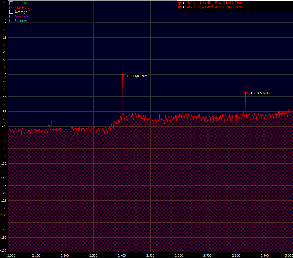
We have found some strange spurs at about TX frequency + 430 MHz (see attached sweep image). This seems not to be the local oscillator which is about 330 Mhz above RX frequency. The spur level is about -23 dBm, much higher than the expected LO leakage.

Can someone explain this strange behavior?

image description

  • Hi, we have made some other tests using also a basic version of the radio_test firmware to perform the TX_CARRIER_TEST. We have removed the attenuator between the nRFGo and the spectrum analyzer and programmed the nRF51 with a TX power of -30 dBm (see attached image).

    This is the code we have used for the test:

    #include <stdint.h>
    #include <stdbool.h>
    #include "boards.h"
    #include "nrf.h"
    #include "nrf51_bitfields.h"
    
    static uint8_t mode_     = RADIO_MODE_MODE_Nrf_1Mbit;
    static uint8_t txpower_  = RADIO_TXPOWER_TXPOWER_Neg30dBm;
    static uint8_t channel_  = 2;
    
    int main(void)
    {
        // Initialization
        NRF_RNG->TASKS_START = 1;    
        // Start 16 MHz crystal oscillator
        NRF_CLOCK->EVENTS_HFCLKSTARTED  = 0;
        NRF_CLOCK->TASKS_HFCLKSTART     = 1;
        // Wait for the external oscillator to start up
        while (NRF_CLOCK->EVENTS_HFCLKSTARTED == 0)
        {
            // Do nothing.
        }
        
        // Radio disable
        NRF_RADIO->SHORTS          = 0;
        NRF_RADIO->EVENTS_DISABLED = 0;
        NRF_RADIO->TEST            = 0;
        NRF_RADIO->TASKS_DISABLE   = 1;
        while (NRF_RADIO->EVENTS_DISABLED == 0)
        {
            // Do nothing.
        }
        NRF_RADIO->EVENTS_DISABLED = 0;
        
        // Perform test
        NRF_RADIO->SHORTS     = RADIO_SHORTS_READY_START_Msk;
        NRF_RADIO->TXPOWER    = (txpower_ << RADIO_TXPOWER_TXPOWER_Pos);    
        NRF_RADIO->MODE       = (mode_ << RADIO_MODE_MODE_Pos);
        NRF_RADIO->FREQUENCY  = channel_;
        NRF_RADIO->TEST       = (RADIO_TEST_CONST_CARRIER_Enabled << RADIO_TEST_CONST_CARRIER_Pos) \
                            | (RADIO_TEST_PLL_LOCK_Enabled << RADIO_TEST_PLL_LOCK_Pos);
    
        NRF_RADIO->TASKS_TXEN = 1;
    
        while(1)
        {
            // Do nothing.
        }
    }
    

    The same spur, as described in the previous post, is still present also with this radio test software.

    Do you have any suggestions/explanations for this radio behaviour?

    image description

    Zoomed image of the spur: image description

  • During TX only there shouldn't be any spur there from the nRF51. The LO is only visible in receive mode. The spur is a little high in frequency as well for receive mode on channel 2.403 MHz. The LO frequency is (8/7)* (2400 + channel_numer + 2). So if you are listening on channel 3 the equation would be: (8/7) * (2400 + 3 +2) ~= 2.748 MHz.

    Could you try reducing the span and "zooming" in on the spur itself. That might give you a more accurate reading for where the spur actually is located and also the level of the spur.

  • Hi, as I have written in my previous posts, we are actually using the nRFGo PCA10005 board (SMA connector), directly connected with the Aaronia HF-60105 spectrum analyzer.

    We have tried 2 different firmware:

    1. a slightly modified version of the DTM firmware (modified to perform only the TRANSMITTER_TEST, without UART communication)

    2. a slightly modified version of the radio_test firmware (modified to perform only the TX_CARRIER_TEST withou UART communication).

    I have posted above the code of the main.c of both firmwares. I have also attached a zoomed image of the measured spur (in the image the nRFGO was set to transmit on frequency 2402MHz).

    Currently we can't understand the spur on TXFreq + 430MHz that appears on the spectrum measurement.

    Do you have a reference test firmware that we could try to load on the nRFGO to perform such test?

    Thanks for your support. Samuele.

  • The DTM test that you are running is just fine and the radio_test is also what we are using. Regarding the zoomed in picture. I mean, are you able to set the span of the measurement equipment to 50 MHz and set the center of the span just over where the spur is? This will help identify where in frequency it accurately is and what the level is. With 1 GHz span it's inaccurate with regard to frequency and also, it could easily be affected by the noise floor. There shouldn't be a spur there from our radio in TX mode, not should there be a spur there if you are in receive mode on channel 2. It could be that the code puts the radio into receive mode on channel 77-78, then you could see such a spur, but not with a 30 dB attenuator. The receiver local oscillator on this board is -56 dBm to -57 dBm, but you need a short span to make the measurement accurate.

  • Hi, we have performed the same tests with another spectrum analyzer and it turns out that the spur that we were observing was introduced by spectrum analyzer! We have used a better spectrum analyzer and with this one the spur is not present anymore... maybe it was due to a problem with the previous spectrum analyzer that we were using.

    Thanks anyway for your support.

Related