This post is older than 2 years and might not be relevant anymore
More Info: Consider searching for newer posts

NRF51 sine wave with pwm and timer

Hi,

I want to generate a sine wave using the nrf pwm library and a timer CC instead of a delay that is used in the sine example here to get better accuracy.

It basically works but I keep getting strange "jumps" in the signal. Here is an image of the signal after an RC filter (5kOhm, 100nF).
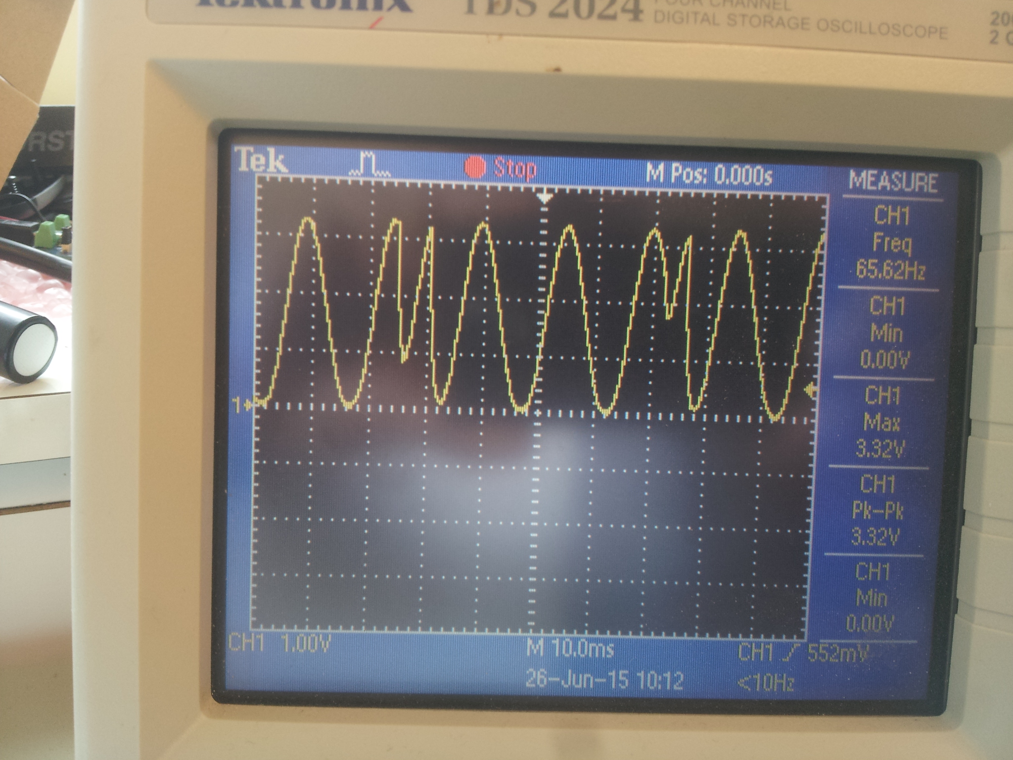
image description

It seems like the phase variable changes value randomly sometimes and I cannot understand why.

Below is my code:

 #include <msp/ble-peripheral/BluetoothPeripheral.h>
#include <msp/drivers/delay.h>
#include <msp/drivers/board_ViTheSSG4rev1.h>

// timer stuff
#include <components/drivers_nrf/hal/nrf_gpiote.h>
#include <components/drivers_nrf/hal/nrf51.h>
#include <components/softdevice/s110/headers/nrf_soc.h>
#include <components/drivers_nrf/hal/nrf51_bitfields.h>

extern "C" {
#include <msp/drivers/nrf_pwm.h>
}

using namespace msp::drivers;

namespace {

uint8_t phase = 0;

bool active = false;

const uint8_t sine26[] = {0, 4, 16, 35, 59, 88, 120, 152, 182, 210, 232, 247,
    255, 255, 247, 232, 210, 182, 152, 120, 88, 59, 35, 16, 4, 0};

}

extern "C" {

void TIMER1_IRQHandler(void) {
  if (active) {
    nrf_pwm_set_value(0, sine26[phase]);
    if (phase < 26) {
      phase += 1;
    } else {
      phase = 0;
    }
  }

//pinToggle(LED_RED);

  NRF_TIMER1->EVENTS_COMPARE[0] = 0; // Clear compare match register

  NRF_TIMER1->TASKS_CLEAR = 1; // Reset timer

}
} // end of extern C

void initPWM(uint8_t pin, nrf_pwm_mode_t nrfPwmMode);
void initTimer(uint16_t frequency);

int main() {
  setupLEDPins();

  pinOutput(PIEZO_PWM_PIN);

// Init softdevice
  BluetoothPeripheral::instance().initialize();

// init pwm
//PWM_MODE_VITHESS_VIBRATOR is 0-255 (8-bit) resolution, 62.5 kHz PWM frequency, 16 MHz timer frequency (prescaler 0)
  initPWM(PIEZO_PWM_PIN, PWM_MODE_VITHESS_VIBRATOR);

  initTimer(128);

  pinClear(LED_GREEN);
  active = true;
  NRF_TIMER1->TASKS_START = 1;               // Start timer.

  while (1) {
    delayMs(1000);
    pinSet(LED_GREEN);
    NRF_TIMER1->TASKS_STOP = 1;
    active = false;
    nrf_pwm_set_value(0, 0);
    delayMs(1000);
    pinClear(LED_GREEN);
    active = true;
    NRF_TIMER1->TASKS_START = 1;               // Start timer.
  }

  return 0;
}

void initPWM(uint8_t pin, nrf_pwm_mode_t nrfPwmMode) {
  nrf_pwm_config_t
  pwm_config = PWM_DEFAULT_CONFIG;

  pwm_config.mode = nrfPwmMode;
  pwm_config.num_channels = 1;
  pwm_config.gpio_num[0] = pin;

// Initialize the PWM library
  nrf_pwm_init (&pwm_config);

// Start the external 16 MHz clock for a more accurate PWM frequency
  NRF_CLOCK->TASKS_HFCLKSTART = 1;
}

void initTimer(uint16_t frequency) {
  NRF_TIMER1->MODE = TIMER_MODE_MODE_Timer;  // Set the timer in Counter Mode
  NRF_TIMER1->TASKS_CLEAR = 1;  // clear the task first to be usable for later
  NRF_TIMER1->PRESCALER = 5; //Set prescaler. Higher number gives slower timer. Prescaler = X gives 16MHz/2^X Hz timer
  NRF_TIMER1->BITMODE = TIMER_BITMODE_BITMODE_16Bit; //Set counter to 16 bit resolution
//NRF_TIMER1->CC[0] = 500000 / (frequency * 26); //Set value for timer compare register 0, timer period is 2us, pwm period is (1/(freq*255)), pwm period/timer period is 15
  NRF_TIMER1->CC[0] = 150; //Set value for timer compare register 0 to 150 as test value

// Enable interrupt on Timer 1,for CC[0]
  NRF_TIMER1->INTENSET = (TIMER_INTENSET_COMPARE0_Enabled
      << TIMER_INTENSET_COMPARE0_Pos);
  sd_nvic_SetPriority(TIMER1_IRQn, 3);
  sd_nvic_EnableIRQ(TIMER1_IRQn);
}

Does anyone understand this behaviour?

Thanks!

  • If you are using softdevice, then it is a known issue devzone.nordicsemi.com/.../ This issue is currently under investigation and we unfortunately have to wait until further information is available.

  • Thanks for your quick reply. Yes, I am using S110.

    Looking forward to a fix in future releases!

  • The way I got round this in order to generate DTMF was to set the maximum count to 400, but limit the on-time to 256. This way I was able to set the next duty cycle in the dead time between 256 and 399. The only IRQ was the one at the 256 count, when I set the compare for the off-time and then looked up the value for next time The downside:

    a) I had to avoid the value of zero for the on-time(I used 1 to 256 rather than 0 to 255)

    b) The resulting voltage levels were not 0 to Vdd(didn't matter in my app.)

    So one compare register is set at 400. This clears the timer(via SHORTS) and toggles the output to ON.

    Another compare register is set to the duty, this toggles the output to OFF.

    A third compare is set to 256, this generates an IRQ in which I update the duty compare with the value I calculated last time, then calc the value for next time.

    Admittedly, I was not running the SD during this, but I reckon that if you can cope with a lower amplitude sine wave, this could still work, you might need to increase the 400 to something higher...

  • Hi John, Thanks for your workaround. I tried to implement it but I am not sure if I understand you correctly, is it something like this you mean:

    namespace {
    
    uint8_t phase = 1;
    
    bool active = false;
    
    const uint8_t sine26[] = {0, 4, 16, 35, 59, 88, 120, 152, 182, 210, 232, 247,
        255, 255, 247, 232, 210, 182, 152, 120, 88, 59, 35, 16, 4, 0};
    
    }
    void initSimplePWM(uint8_t pin);
    
    extern "C" {
    
    void TIMER2_IRQHandler(void) {
      NRF_TIMER2->CC[0] = sine26[phase];
      if (phase < 26) {
        phase++;
      } else {
        phase = 1;
      }
    }
    
    } // end of extern C
    
    int main() {
      setupLEDPins();
    
      pinOutput(PIEZO_PWM_PIN);
    
    // Init softdevice
      BluetoothPeripheral::instance().initialize();
    
      initSimplePWM(PIEZO_PWM_PIN);
      NRF_TIMER2->TASKS_START = 1;               // Start timer.
    
      while (1) {
        delayMs(100);
        pinToggle(LED_RED);
      }
      
      return 0;
    }
    
    void initSimplePWM(uint8_t pin) {
      // Configure GPIOTE channel 0 and 1 to change pin state
      nrf_gpiote_task_config(0, pin, NRF_GPIOTE_POLARITY_LOTOHI,
          NRF_GPIOTE_INITIAL_VALUE_LOW);
    
      nrf_gpiote_task_config(1, pin, NRF_GPIOTE_POLARITY_HITOLO,
          NRF_GPIOTE_INITIAL_VALUE_LOW);
    
      // Configure PPI channel 0 to toggle PWM_OUTPUT_PIN on every TIMER2 COMPARE[0] match.
      NRF_PPI->CH[0].EEP = (uint32_t)&NRF_TIMER2->EVENTS_COMPARE[0];
      NRF_PPI->CH[0].TEP = (uint32_t)&NRF_GPIOTE->TASKS_OUT[0];
      NRF_PPI->CH[1].EEP = (uint32_t)&NRF_TIMER2->EVENTS_COMPARE[1];
      NRF_PPI->CH[1].TEP = (uint32_t)&NRF_GPIOTE->TASKS_OUT[1];
    
      // Enable PPI channel 0.
      NRF_PPI->CHEN = (PPI_CHEN_CH0_Enabled << PPI_CHEN_CH0_Pos |
      PPI_CHEN_CH1_Enabled << PPI_CHEN_CH1_Pos);
      //sd_ppi_channel_enable_set(1 << 0);
    
      // Init TIMER2 for 10kHz PWM
      NRF_TIMER2->MODE = TIMER_MODE_MODE_Timer;     // Set the timer in Counter Mode
      NRF_TIMER2->TASKS_CLEAR = 1;   // Clear the tasks first to be usable for later
      NRF_TIMER2->PRESCALER = 4; // 2^PRESCALER (values authorized 1 to 9) 4 : 16MHz / 16 = 1MHz
      NRF_TIMER2->BITMODE = TIMER_BITMODE_BITMODE_16Bit; //Set counter to 16 bit resolution
      NRF_TIMER2->CC[0] = phase; //1Mhz timer with prescaler 4
      NRF_TIMER2->CC[1] = 400; //1Mhz timer with prescaler 4
      NRF_TIMER2->CC[2] = 256; //1Mhz timer with prescaler 4
      NRF_TIMER2->SHORTS = (TIMER_SHORTS_COMPARE1_CLEAR_Enabled
          << TIMER_SHORTS_COMPARE1_CLEAR_Pos);
    
      NRF_TIMER2->INTENSET = (TIMER_INTENSET_COMPARE2_Enabled
          << TIMER_INTENSET_COMPARE2_Pos);
      sd_nvic_SetPriority(TIMER2_IRQn, 3);
      sd_nvic_EnableIRQ(TIMER2_IRQn);
    }
    

    This code does not work but if this is what you meant and you got it to work I will continue on this path as there does not seem to be any other way to generate a sine wave output with the nrf51 device.

  • OK Here is my code. Bear in mind that I am generating two sine waves, and I am using a fractional accumulator method(or whatever it's called) This is completely self contained, i.e. all the setting up and clearing up is in this function. As I said, I do not have the SD running at this point, but if I were you I'd get it working without first, then see if you can make it work with the SD.

    #include "dtmf.h"
    #include "nrf_gpiote.h"
    #include "nrf.h"
    #include "nrf51_bitfields.h"
    #include "nrf_soc.h"
    #include "nrf_gpio.h"
    
    
    #define	DIGIT_LEN	100000/20		// 100 mS, PWM max is 20uS
    #define	GAP_LEN		100000/20		// 100 mS
    
    #define GPIOTE_CHAN_FOR_PWM_TASK	3	//The GPIOTE Channel used for PWM
    #define DTMF_TIMER	NRF_TIMER1		// Timer used
    
    
    enum
    {
    DTMF_1, DTMF_2, DTMF_3, DTMF_A,
    DTMF_4, DTMF_5, DTMF_6, DTMF_B,
    DTMF_7, DTMF_8, DTMF_9, DTMF_C,
    DTMF_STAR, DTMF_0, DTMF_HASH, DTMF_D
    };
    
    #define HF1663	(1663 * 32678 + 20000) / 40000
    #define HF1477	(1477 * 32678 + 20000) / 40000
    #define HF1336	(1336 * 32678 + 20000) / 40000
    #define HF1209	(1209 * 32678 + 20000) / 40000
    
    #define LF941	(941 * 32678 + 20000) / 40000
    #define LF852	(852 * 32678 + 20000) / 40000
    #define LF770	(770 * 32678 + 20000) / 40000
    #define LF697	(697 * 32678 + 20000) / 40000
    
    const uint16_t HighGroup [4] =
    	{
    	HF1209,
    	HF1336,
    	HF1477,
    	HF1663
    	};
    const uint16_t LowGroup [4] =
    	{
    	LF697,
    	LF770,
    	LF852,
    	LF941
    	};
    
    const uint8_t SineTable [128] = {
    	0,0,0,0,1,1,2,3,
    	4,6,7,9,10,12,14,16,
    	18,21,23,25,28,31,33,36,
    	39,42,45,48,51,54,57,60,
    	64,67,70,73,76,79,82,85,
    	88,91,94,96,99,102,104,106,
    	109,111,113,115,117,118,120,121,
    	123,124,125,126,126,127,127,127,
    	127,127,127,127,126,126,125,124,
    	123,121,120,118,117,115,113,111,
    	109,106,104,102,99,96,94,91,
    	88,85,82,79,76,73,70,67,
    	64,60,57,54,51,48,45,42,
    	39,36,33,31,28,25,23,21,
    	18,16,14,12,10,9,7,6,
    	4,3,2,1,1,0,0,0
    	};
    
    void SendDTMF(uint8_t code)
    {
    uint16_t StepLo = 0;
    uint16_t StepHi = 0;
    uint16_t SineIndexLo = 0;
    uint16_t SineIndexHi = 0;
    uint16_t pwm_value = 1;
    uint8_t temph;
    uint8_t templ;
    uint16_t duration;
    nrf_gpio_cfg_output(PWM_OUT);
    nrf_gpio_cfg_output(DTMF_LED);
    
    // Set up the PPI
    // PPI channel 0 event is Timer1 compare 2
    NRF_PPI->CH[0].EEP = (uint32_t) &DTMF_TIMER->EVENTS_COMPARE[2];
    
    // PPI channel 0 task is GPIOTE task 3(toggle output)
    NRF_PPI->CH[0].TEP = (uint32_t) &NRF_GPIOTE->TASKS_OUT[3];
    
    // PPI chan 1 event is Timer n compare 0
    NRF_PPI->CH[1].EEP = (uint32_t) &DTMF_TIMER->EVENTS_COMPARE[0];
    
    // PPI chan 1 task is GPIOTE task 3(toggle output)
    NRF_PPI->CH[1].TEP = (uint32_t) &NRF_GPIOTE->TASKS_OUT[3];
    
    // Enable PPI chan 0
    NRF_PPI->CHENSET = (1 << 0);
    
    // Enable PPI chan 1
    NRF_PPI->CHENSET = (1 << 1);
    
    DTMF_TIMER->MODE = TIMER_MODE_MODE_Timer;    // Set the timer in Timer Mode.
    DTMF_TIMER->PRESCALER = 0; // Prescaler 0 produces 16mHz Hz timer frequency => 1 tick = 62.5nS.
    DTMF_TIMER->BITMODE = TIMER_BITMODE_BITMODE_16Bit;  // 16 bit mode.
    DTMF_TIMER->TASKS_CLEAR = 1; // clear the task first to be usable for later.
    
    DTMF_TIMER->CC[0] = 1;		// cc 0 is the end of the PWM ON period, avoid zero
    DTMF_TIMER->CC[1] = 255;	// cc 1 is the point where we update the period (cc0)
    DTMF_TIMER->CC[2] = 399;	//319;	// cc 2 is the point where we clear the counter and set the PWM out high
    // cc2 clears the counter
    DTMF_TIMER->SHORTS = TIMER_SHORTS_COMPARE2_CLEAR_Msk;
    
    // Configure the GPIOTE Task to toggle the PWM output.
    nrf_gpiote_task_config(GPIOTE_CHAN_FOR_PWM_TASK,
                               PWM_OUT,
                               NRF_GPIOTE_POLARITY_TOGGLE,
                               NRF_GPIOTE_INITIAL_VALUE_HIGH);
    
    StepLo = LowGroup[code >> 2 & 3];
    StepHi = HighGroup[code & 3];
    
    duration = DIGIT_LEN + GAP_LEN;
    DTMF_TIMER->TASKS_START = 1;  // Start timer.
    
    nrf_gpio_pin_set(DTMF_LED);
    
    // Because my app was doing nothing else I polled the timer compare
    // but it should work as an IRQ
    while(duration)
        {
        if(DTMF_TIMER->EVENTS_COMPARE[1])
    	{
    	DTMF_TIMER->CC[0] = pwm_value;
    	DTMF_TIMER->EVENTS_COMPARE[1] = 0;
    	// Now calculate value for next time time.
    	// Move pointers a step width ahead
    	SineIndexHi += StepHi;
    	SineIndexLo += StepLo;
    	temph = SineTable[SineIndexHi >> 8 & 127];
    	templ = SineTable[SineIndexLo >> 8 & 127];
    	templ -= (templ >> 2);		// Low * 0.75
    	temph += templ;
    	// Avoid a zero value. I can do this safely as the sine table only goes up to 127
    	// and the lower of the two tones has been multiplied by 0.75 abave
    	temph += 1;
    	pwm_value = (uint16_t)temph;
    
    	if(duration == GAP_LEN)
    	    {
    	    nrf_gpio_pin_clear(DTMF_LED);	// This turns off the LED after 50mS or so
    	    }
    	if(duration < GAP_LEN)
    		{
    		if(temph == 1)			// This is because I want to turn the tones off when the output is close to 0V
    			{
    			StepHi = 0;
    			StepLo = 0;
    			nrf_gpiote_unconfig(GPIOTE_CHAN_FOR_PWM_TASK);
    		        nrf_gpio_pin_write(PWM_OUT, 0);
    			}
    		}
    	if(duration)
    		{
    		duration--;
    		}
    	}
        }// ends while(duration)
    
    // Dismantle everything
    DTMF_TIMER->TASKS_STOP = 1;  // Stop timer.
    DTMF_TIMER->TASKS_CLEAR = 1;  // Clear timer.
    DTMF_TIMER->SHORTS = 0x00;
    DTMF_TIMER->EVENTS_COMPARE[0] = 0;
    DTMF_TIMER->EVENTS_COMPARE[1] = 0;
    DTMF_TIMER->EVENTS_COMPARE[2] = 0;
    
    // Disable PPI chan 0
    NRF_PPI->CHENCLR = (1 << 0);
    // Disable PPI chan 1
    NRF_PPI->CHENCLR = (1 << 1);
    }
    
Related