This post is older than 2 years and might not be relevant anymore
More Info: Consider searching for newer posts

nRF51 and MPU6050 TWI Issue

Hi,

I've looked at the example codes provided by Martin in these two topics for communicating to a MPU6050 through TWI:

1- devzone.nordicsemi.com/.../ (uses SDK 9) 2- devzone.nordicsemi.com/.../ (uses SDK 10)

Just for others to know: The first one is just a TWI example, and the second one has a set of functions added for MPU9150/MPU6050. I found the only difference between SDK 9 and 10 in the nrf_drv_twi_init function, which needs 3 parameters in SDK 9 and 4 parameters in SDK 10. Also, I paid attention to TWI instance used in NRF_DRV_TWI_INSTANCE, and enabled it in nrf_drv_config.

I'm in process of trouble shooting this and any comments can help. Here are what I observed by using the codes above in my project on a PCA20006 with 3rd revision IC and SDK 9. Similar to 2, I only use twi_init(), mpu_init() and then just a couple of readings.

1- Without connecting the MP board, I added a blinking LED code in mpu9150_twi_event_handler which is called by twi_handler. This is added under "case NRF_DRV_TWI_ERROR". As there is no device on TWI, program goes to this error case and LED blinks.

2- When connecting the MPU board, the program doesn't go to the error case at all, and also exactly after using mpu_init(), the current of MPU board goes from 0 to 3~4 mA. So, I thought the TWI is working. BUT,

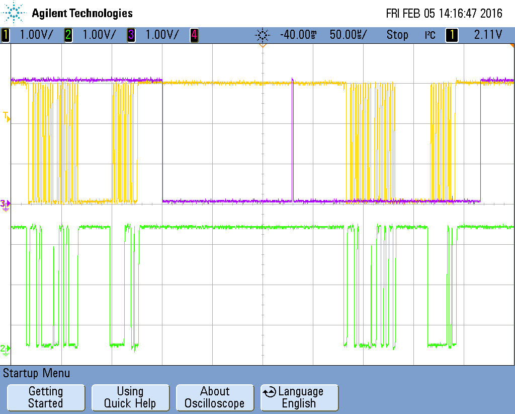
3- I added an IO pin toggle for 10usec, under "case NRF_DRV_TWI_TX_DONE". Similar to the TWI example by Martin I expected that after a successful TX, it should go to that case and toggle the pin. But, this doesn't happen + when I monitor the SCL and SDA pins it seems that they are always "HIGH".

From one hand, it seems that two boards are actually communicating as compared to "no MPU case", the code never goes to the error case. On the other hand it doesn't go to TX_DONE case either and it seems that the pins are not changing.

Any comments?

BTW, SDA and SCL lines are pulled up in MPU6050 board to its VLOGIC=3V by 2K resistors.

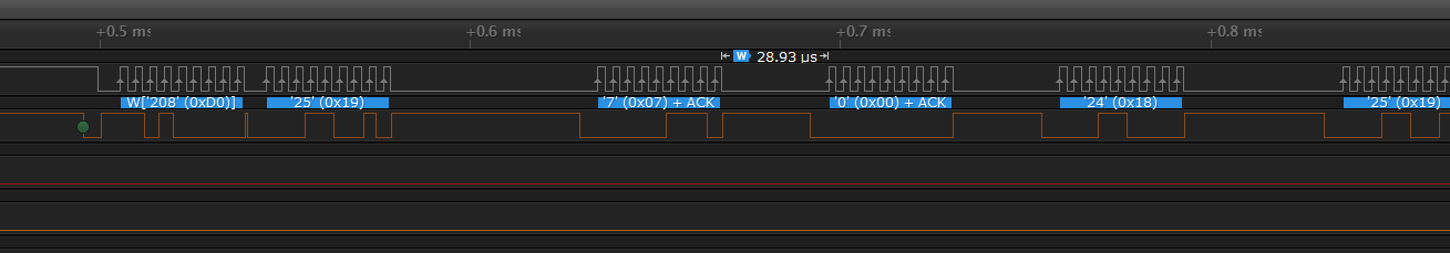
Update 1 - Oscilloscope screen shot with MPU9150_TWI_TIMEOUT = 5000 - See Comments for more information image description

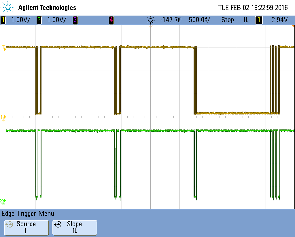
Update 2 - Screen shot with MPU9150_TWI_TIMEOUT = 1000 with an IO pin toggling after each NRF_DRV_TWI_RX_DONE event image description

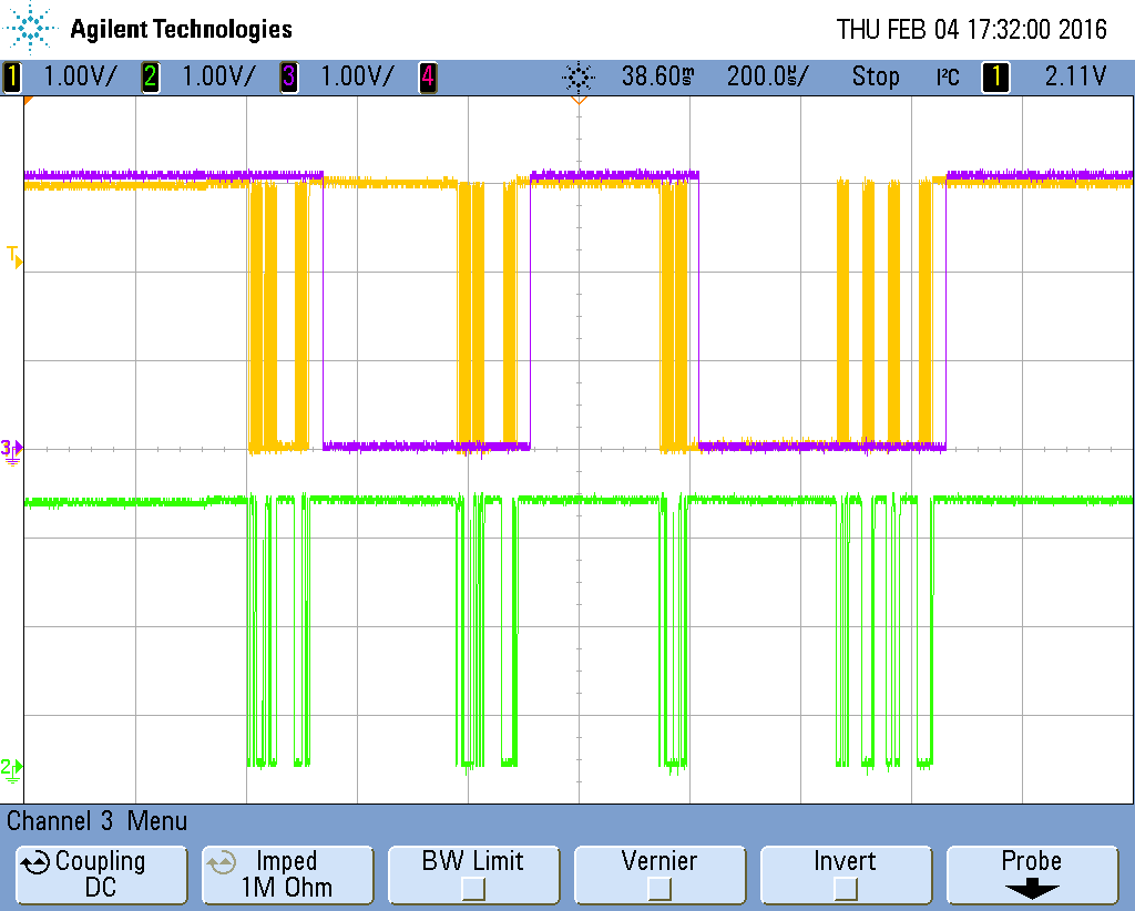
Update 3 - Screen shot with MPU9150_TWI_TIMEOUT = 750 with an IO pin toggling after each NRF_DRV_TWI_RX_DONE event + IO pin toggle after the while loop + conditional toggle based on twi_tx_done image description

main.c mpu9150.c mpu9150.h

  • Hi,

    I ported the github MPU9150 example to SDK 9 (quick and dirty, but at least it works on my MPU9150). Here is the ported example.

    A few questions:

    1. Are you able to run the simple TWI example (without the MPU drivers) and get a response from your MPU? I.e. can you confirm that the MPU is working? If I understand you correctly you are able to communicate with it, but I still have to ask; are you using the correct pins?
    2. How are you monitoring the TWI pins? Do you have a logic trace so you are absolutely sure that nothing happens on the TWI lines?
    3. Maybe you can post your code? You can do it on our Support Portal if you want some confidentiality.
  • Hi Martin, thanks for your response and the example in SDK 9. I figured out the problem was maybe due to the 10usec toggling code in the twi_tx_done + setting the oscilloscope to capture the few transitions. So, now I can see that the code goes to twi_tx_done and SCL/SDA pins are changing as shown in the attached picture. I have one other question about the timing of TWI events in this code, which maybe is good to have it answered in this topic: You can see a constant separation between TWI events, e.g., the above picture shows 4 writes to 4 different registers in the MPU and there is around 1.3msec between them. I saw a similar separation during twi_read between sending the register address and receiving its value. Is this something related to the nRF TWI driver or MPU? Which parameter controls it?

  • I'm not seeing such delays. Here is my trace of the transmissions happening in mpu9150_config(): image description

    As you can see there is only a 28.93us delay. Do you do anything in your TWI handler that might take time?

  • Only in case of an error, yes, an LED blinks for 3 sec.

    void mpu9150_twi_event_handler(const nrf_drv_twi_evt_t *evt)
    { 
        switch(evt->type)
        {
            case NRF_DRV_TWI_TX_DONE:
                twi_tx_done = true;
                nrf_gpio_pin_toggle(0);
                break;
            case NRF_DRV_TWI_RX_DONE:
    						 twi_rx_done = true;
    						 nrf_gpio_pin_toggle(20);
                break;
            case NRF_DRV_TWI_ERROR:
    						for(uint8_t i=1; i<4; i++) {
    							 gpio_blink2(1000);
    							 }
                switch(evt->error_src)
                {
                    case NRF_TWI_ERROR_ADDRESS_NACK:
                        break;
                    case NRF_TWI_ERROR_OVERRUN_NACK:
                        break;
                    case NRF_TWI_ERROR_DATA_NACK:
                        break;
                    default:
                        break;
                }
                break;
            default:
                break;
        }        
    }
    
  • Hi again! In your trace we should look at the gap around 0.6msec, which is between writing address (0x19) and writing the first byte (0x07). Still the delay is around 50usec. I started playing with MPU9150_TWI_TIMEOUT, which was 5000 in previous code and is 4000+1 in the new code you posted here. To me this just looked like a maximum wait time to generate an error in I2C read/write functions. But as you can see in the 2nd trace when I changed it to 1000, the delay dropped to around 250usec. I was getting some TWI errors when I used 500 and will test it again. Any thoughts why is this happening? I'm attaching the main function and MPU files. Main is using the same functions you are using and I checked all the used functions in MPU files and they are the same as yours. My whole project files are not still well documented, so it might be confusing to post, but that might be our last resort.

Related