This post is older than 2 years and might not be relevant anymore
More Info: Consider searching for newer posts

nRF52832- why when using nrf_drv_spi with an ADXL362 I need to set the clock in high drive (H0H1)

Hello!

I am working on a project. The goal is to retrieve every seconds some acceleration data from the ADXL362 accelerometer.

I configured the spi in blocking mode by passing NULL as event handler nrf_drv_spi_init(_spi, &_spi_config, NULL);

This method will use the information inside the _spi_config structure to set the pins with this configuration:

PIN_CNF[MOSI] = 0x00000003
direction:output, input: disconnect, pull: disabled, drive: S0S1, sense: disabled

PIN_CNF[MISO] = 0x00000000
direction:input, input: connect, pull: disabled, drive: S0S1, sense: disabled

PIN_CNF[CLK] = 0x00000001
direction:output, input: connect, pull: disabled, drive: S0S1, sense: disabled

PIN_CNF[SS] = 0x00000003
direction:output, input: disconnect, pull: disabled, drive: S0S1, sense: disabled

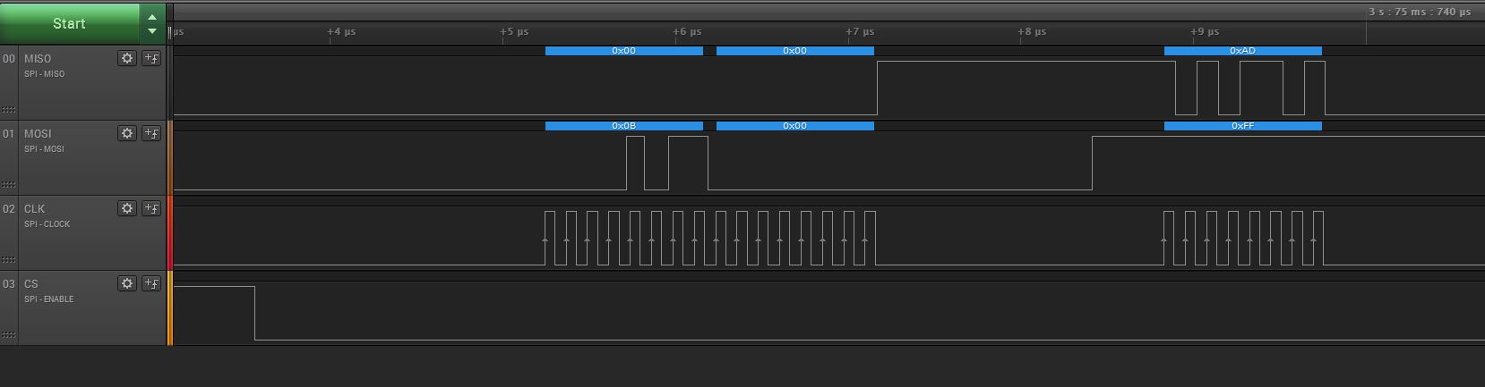
But when I try a dummy transaction like read (0x0B) the register with the acceleromter ID (0x00), I should have 0xAD.

Instead I have this: image description

S0S1.JPG

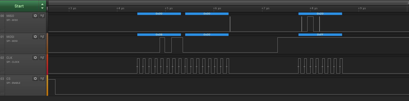
I thought that The MISO pin was not really disconnected but after several tries I found that if I modify the clock pin config to work in high drive:

PIN_CNF[CLK] = 0x00000301
direction:output, input: connect, pull: disabled, drive: H0H1, sense: disabled

I have now a good communication transaction with the accelerometer: image description

H0H1.JPG

Any idea why the clock config influence the MISO signal?

My project need to be low power, therefore I should not use the clock pin in high drive mode.

Another guy have the same problem: devzone.nordicsemi.com/.../

Thanks for your help,

Cyril Praz

  • Here is the answer from a nordic application engineer:

    Hi,

    Comparing the rise and fall time of a GPIO on the nRF51 vs. the nRF52, that data is not easily available. Although nRF52 uses a similar architecture the actual pad drivers are very different (since nRF51 use 180nm vs nRF52 use 55nm).

    Simulation on a large capacitor load (100nF @ 3V) show that the rise and fall time on the nRF52 is almost 3x that of nRF51 (60ns->150ns). So it might be that the nRF51 just were able to meet the requirement in standard drive, but on the nRF52 you need to use high drive. Overall though I don't expect using high drive will increase current consumption, as it only affect the rise and fall times (you are not loading the line with resistive load).

    Best regards,

    Kenneth

  • I have a similar problem: devzone.nordicsemi.com/.../

    I have noticed that if I perform a softreset on ADXL362, next time I restart the nRF52 keeping the UART connected (RX/TX pins @3.3V), the system does not reset properly and reading from any of the ADXL's registers will return 0x00. When I skip the soft reset, the above mentioned problem does not occur on reboot. But another one happens: the ADXL does not trigger any interrupt after rebooting.

    In both cases I can solve the problem by disconnecting UART cable, powering off, reconnecting UART cable and powering on the system.

    I tried forcing H0H1 and NRF_DRV_SPI_MODE_x (x=0,1,2,3), with no luck.

    Does anyone have any idea why this happens?

    Thank you, Marco

  • The ADXL362 has specific power supply startup requirements - see page 37 in the (Rev-E) datasheet.

    In particular, you have to ensure that the supply falls properly to 0V ...

  • I have been so busy investigating internal registers and SPI and UART configuration that I was giving for granted the hardware design. Thank you Awneil, this is a relevant point :)

  • I have been facing this issue again. In my case I have fixed it by:

    • setting SPI CLK in either GPIO_PIN_CNF_DRIVE_H0S1 or GPIO_PIN_CNF_DRIVE_H0H1
    • and setting input SPI MISO with NRF_GPIO_PIN_PULLUP This is required when using ADXL362 on external chip connected via nRD52 DK GPIO pins. I will do additional test on my custom PCB with both nRF52 and ADXL362 onboard. Cheers, Marco
Related