nRF52 Zephyr VSCode DeviceTree

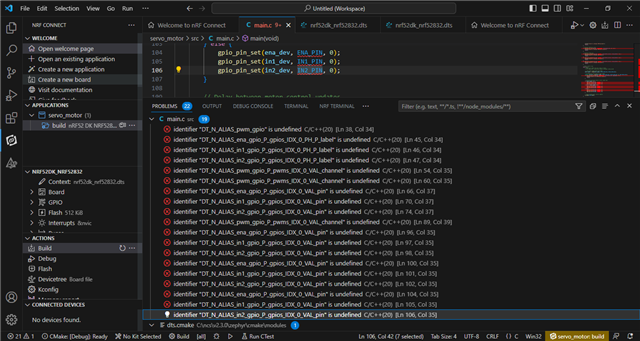
Hello everyone. I've started coding with Zephyr on my nRF52 device. I'm relatively new to this. I'm trying to drive a DC motor with L298N. However, I have no idea how to configure the pin settings in the device tree. I have defined the motor pins in the device tree, but when I try to use them in main.c, I get an error saying they are not defined. Can someone help me understand how to use the device tree? Thank you.

  • Hi,

    Could you show me how you are defining the pins?
    How do you intend to use them in your application?
    Would you like to define some of them as PWM pins?

  • #include <zephyr/kernel.h>
    #include <zephyr/sys/printk.h>
    #include <zephyr/device.h>
    #include <zephyr/drivers/pwm.h>
    #include <zephyr/drivers/gpio.h>
    
    
    #define PWM_PERIOD_USEC 2000
    
    #define ENA_PIN DT_GPIO_PIN(DT_ALIAS(ena_gpio), gpios)
    #define IN1_PIN DT_GPIO_PIN(DT_ALIAS(in1_gpio), gpios)
    #define IN2_PIN DT_GPIO_PIN(DT_ALIAS(in2_gpio), gpios)
    
    #define PWM_DEV DT_PWMS_LABEL(DT_ALIAS(pwm_gpio))
    #define PWM_CHANNEL DT_PWMS_CHANNEL(DT_ALIAS(pwm_gpio))
    
    #define MOTOR_SPEED_MIN -100
    #define MOTOR_SPEED_MAX 100
    
    void main(void)
    {
    struct device *pwm_dev, *ena_dev, *in1_dev, *in2_dev;
    int motor_speed = 0;
    
    pwm_dev = device_get_binding(PWM_DEV);
    if (!pwm_dev) {
    printk("Failed to open PWM device\n");
    return;
    }
    
    ena_dev = device_get_binding(DT_GPIO_LABEL(DT_ALIAS(ena_gpio), gpios));
    in1_dev = device_get_binding(DT_GPIO_LABEL(DT_ALIAS(in1_gpio), gpios));
    in2_dev = device_get_binding(DT_GPIO_LABEL(DT_ALIAS(in2_gpio), gpios));
    if (!ena_dev || !in1_dev || !in2_dev) {
    printk("Failed to open GPIO devices\n");
    return;
    }
    
    if (pwm_pin_set_usec(pwm_dev, PWM_CHANNEL, PWM_PERIOD_USEC, 0) < 0) {
    printk("Failed to configure PWM period\n");
    return;
    }
    
    if (pwm_pin_set_usec(pwm_dev, PWM_CHANNEL, PWM_PERIOD_USEC, 0) < 0) {
    printk("Failed to configure PWM duty cycle\n");
    return;
    }
    
    if (gpio_pin_configure(ena_dev, ENA_PIN, GPIO_OUTPUT_ACTIVE | GPIO_OUTPUT) < 0) {
    printk("Failed to configure ENA pin\n");
    return;
    }
    if (gpio_pin_configure(in1_dev, IN1_PIN, GPIO_OUTPUT_ACTIVE | GPIO_OUTPUT) < 0) {
    printk("Failed to configure IN1 pin\n");
    return;
    }
    if (gpio_pin_configure(in2_dev, IN2_PIN, GPIO_OUTPUT_ACTIVE | GPIO_OUTPUT) < 0) {
    printk("Failed to configure IN2 pin\n");
    return;
    }
    
    while (1) {
    
    motor_speed = clamp(motor_speed, MOTOR_SPEED_MIN, MOTOR_SPEED_MAX);
    
    uint32_t pwm_duty = map(motor_speed, MOTOR_SPEED_MIN, MOTOR_SPEED_MAX, 0, PWM_PERIOD_USEC);
    if (pwm_pin_set_usec(pwm_dev, PWM_CHANNEL, PWM_PERIOD_USEC, pwm_duty) < 0) {
    printk("Failed to set PWM duty cycle\n");
    return;
    }
    
    if (motor_speed > 0) {
    gpio_pin_set(ena_dev, ENA_PIN, 1);
    gpio_pin_set(in1_dev, IN1_PIN, 1);
    gpio_pin_set(in2_dev, IN2_PIN, 0);
    } else if (motor_speed < 0) {
    gpio_pin_set(ena_dev, ENA_PIN, 1);
    gpio_pin_set(in1_dev, IN1_PIN, 0);
    gpio_pin_set(in2_dev, IN2_PIN, 1);
    } else {
    gpio_pin_set(ena_dev, ENA_PIN, 0);
    gpio_pin_set(in1_dev, IN1_PIN, 0);
    gpio_pin_set(in2_dev, IN2_PIN, 0);
    }
    
    k_sleep(K_MSEC(100));
    }


    This is my main code.

    / {
        aliases {
            pwm_gpio = &pwm_led0;
            ena_gpio = &motor_en;
            in1_gpio = &motor_in1;
            in2_gpio = &motor_in2;
        };
    
        pwm_led0: pwm-led0 {
    		compatible = "pwm-leds";
    		pwms = <&pwm0 0 1000000>;
    		status = "okay";
    	};
    	
    	motor_en: motor_en {
    		compatible = "gpio-keys";
    		gpios = <&gpio0 7 GPIO_ACTIVE_HIGH>;
    		
    	};
    	
    	motor_in1: motor_in1 {
    		compatible = "gpio-keys";
    		gpios = <&gpio0 6 GPIO_ACTIVE_HIGH>;
    		
    	};
    	
    	motor_in2: motor_in2 {
    		compatible = "gpio-keys";
    		gpios = <&gpio0 8 GPIO_ACTIVE_HIGH>;
    	
    	};
    };

    The code I wrote for this device tree file
    And the error
    I need to define 3 pins for the motor driver. I also need to define a PWM pin for driving the motor.
  • I see. pwm-leds and gpio-keys both need their LEDs and GPIOs to be child nodes. This should be valid for the device tree:

    / {
        aliases {
            pwm_gpio = &pwm_led0;
            ena_gpio = &motor_en;
            in1_gpio = &motor_in1;
            in2_gpio = &motor_in2;
        };
        
        /delete-node/ pwmleds;
        
        motor_pwm {
            compatible = "pwm-leds";
            pwm_led0: pwm_led0 {
        		pwms = <&pwm0 0 1000000>;
        		status = "okay";
        	};
        };
    	
    	motor_gpios {
    	    compatible = "gpio-keys";
        	motor_en: motor_en {
        		gpios = <&gpio0 7 GPIO_ACTIVE_HIGH>;
        		
        	};
        	
        	motor_in1: motor_in1 {
        		gpios = <&gpio0 6 GPIO_ACTIVE_HIGH>;
        		
        	};
        	
        	motor_in2: motor_in2 {
        		gpios = <&gpio0 8 GPIO_ACTIVE_HIGH>;
        	
        	};
        };
    };

    I added a line to delete the pwmleds node to avoid any potential conflict with motor_pwm.

  • I see. Thank you.I changed the device tree code now but I keep getting the errors in the photo I shared above.What is the reason for these errors?

  • There's probably some issue with your DT macros then. Which version of the SDK are you using? And which DK?

Related