nrf52832 SPIM Driver "Missing" MISO Bits

Hi All,

I am running into an issue where the data returned from nrfx_spim_xfer() does not match what is being transmitted on the line. More details below.

MCU: nrf52832
SDK: nRF5 17.1.0

IDE: Segger 5.70a

Here is an example of the issue. When trying to read a register of an AFE using SPI, we can see this data being transmitted using a logic analyzer:

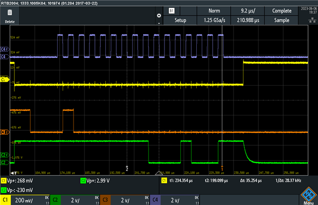
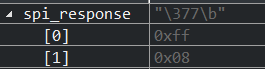
As shown in the scope screenshot, it would appear that the data on the MISO line (green plot in picture), would represent a value of 0xFF then 0x89. In the debugger, the data that appears in the rx_buffer appears as so:

This issue occurs on several different occasions, where 1 or 2 HIGH bits appear to be missed. 

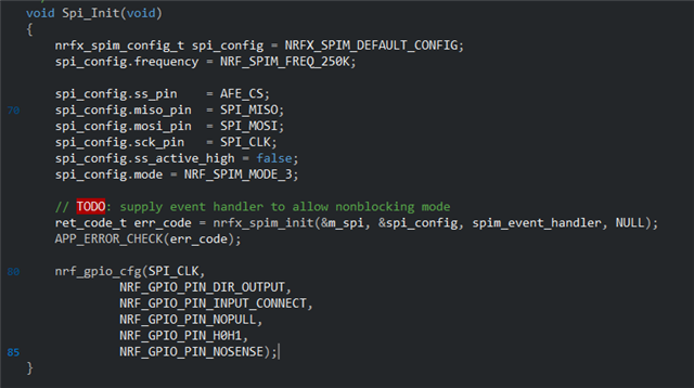
Below are the SPI init settings being used:

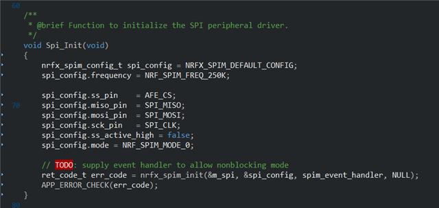
SPI Mode 0 was confirmed to us by the AFE manufacturer to be the correct SPI mode for the device. Let me know if any other information would be helpful, thanks!

  • Attached are 3 files. app.c is where the SPI init and ad7785 init functions are called. ad7785_init is where the SPI transactions in question are called. spi_driver.c is where nrfx_spim_xfer() is called. 

    /** 
     * @file app.c
     */
    
    #include "app.h"
    
    APP_TIMER_DEF(m_afe_sample_timer);       /**< Periodic timer instance declaration */
    
    /**
     * Local function to call power up sequence
     */
    void power_up_sequence(void)
    {
        nrf_delay_ms(10);                //generic board power up delay
    }
    
    /**@brief Function for initializing the nrf log module.
     */
    static void log_init(void)
    {
        ret_code_t err_code = NRF_LOG_INIT(NULL);
        APP_ERROR_CHECK(err_code);
    
        NRF_LOG_DEFAULT_BACKENDS_INIT();
    }
    
    /**@brief Function for initializing power management.
     */
    static void power_management_init(void)
    {
        ret_code_t err_code;
        err_code = nrf_pwr_mgmt_init();
        APP_ERROR_CHECK(err_code);
    }
    
    /**@brief Function for the Timer initialization.
     *
     * @details Initializes the timer module. This creates and starts application timers.
     */
    static void timers_init(void)
    {
        // Initialize timer module.
        ret_code_t err_code = app_timer_init();
        APP_ERROR_CHECK(err_code);
    
        // Create timers.
    
        /* YOUR_JOB: Create any timers to be used by the application.
                     Below is an example of how to create a timer.
                     For every new timer needed, increase the value of the macro APP_TIMER_MAX_TIMERS by
                     one.
           ret_code_t err_code;
           err_code = app_timer_create(&m_app_timer_id, APP_TIMER_MODE_REPEATED, timer_timeout_handler);
           APP_ERROR_CHECK(err_code); */
    
        err_code = app_timer_create(&m_afe_sample_timer, APP_TIMER_MODE_REPEATED, Afe_Sampling_Task_Timer_Handler);
        APP_ERROR_CHECK(err_code);
    }
    
    /**@brief Function to start basic app timers.
     */
    static void timers_start(void)
    {
        ret_code_t err_code;
        err_code = app_timer_start(m_afe_sample_timer, AFE_SAMPLING_PERIOD, NULL);
    }
    
    /**
     * Local function to call the inits for all of the peripheral drivers
     */
    void peripheral_drivers_init(void)
    {
        /*Initialize Nordic Peripheral Drivers***************************/
    
        //Not currently using ADC
        //Adc_Init();
        
        //Not currently using I2C
        //I2c_Init();
    
        Spi_Init();   //Communication with the AD7785 AFE
    
        Pwm_Init();   //Controls the two RGB LEDs
    
        /*Initialize TRI-SSM Peripheral Hardware Drivers*****************/
        bool config_error = false;
    
        config_error |= Ad7785_Init();    //Initialize AD7785 AFE
    
        if (config_error)
        {
            Led1_Color_Set(COLOR_RED);
            Led2_Color_Set(COLOR_RED);
        }else{
            Led1_Color_Set(COLOR_GREEN);
            Led2_Color_Set(COLOR_GREEN);
        }
    }
    
    
    /**
     * Global function to call to initialize the application structures/state machines/etc.
     */
    void App_Init(void)
    {
        power_up_sequence();
    
        log_init();
    
        power_management_init();
    
        timers_init();
    
        peripheral_drivers_init();
    
        Ble_Drivers_Init();
    
        APP_SCHED_INIT(SCHED_MAX_EVENT_DATA_SIZE, SCHED_QUEUE_SIZE);
    
        timers_start();
    }
    /** 
     * @file ad7785.c
     */
    
    #include "ad7785.h"
    
    void ad7785_spi_reset(void)
    {
        uint8_t spi_command[4] = {0};
        uint8_t spi_response[4] = {0};
        static bool success = false;
    
        //Send read command to COMMS reg
        memset(spi_command, 0xff, sizeof(spi_command));
    
        success = Spi_Transfer(spi_command, spi_response, 4, 4);
    }
    
    bool ad7785_id_check(void)
    {
        uint8_t spi_command[2] = {0};
        uint8_t spi_response[2] = {0};
        static bool success = false;
    
        //Send read command to COMMS reg
        memset(spi_command, 0x00, sizeof(spi_command));
        memset(spi_response, 0x00, sizeof(spi_command));
        spi_command[0] = (AFE_READ_BITS << 6) |
                         (AFE_STATUS_REG_BITS << 3) |
                         (AFE_CR1_CR0_BITS);
        success = Spi_Transfer(spi_command, spi_response, 2, 2);
    
        spi_response[1] = (spi_response[1] & 0x0F);
    
        if(spi_response[1] == AD7785_ID)
        {
            return false;
        }else{
            return true;
        }
    }
    
    bool Ad7785_Init(void)
    {
        bool config_error = false;
        
        ad7785_spi_reset();
    
        config_error |= ad7785_id_check();
    
        return config_error;
    }
    /* INCLUDES ************************************************/
    #include "spi_driver.h"
    #include "nrf_delay.h"
    #include "nrf_log.h"
    #include "nrf_gpio.h"
    #include "TRI_SSM_REV_A.h"
    
    #include "nrf_delay.h"
    
    #define SPI_INSTANCE  1 /**< SPI instance index. */
    static const nrfx_spim_t m_spi = NRFX_SPIM_INSTANCE(SPI_INSTANCE);    /**< SPI instance declaration */
    static volatile bool spi_xfer_done;  /**< Flag used to indicate that SPI instance completed the transfer. */
    
    #define TEST_STRING "Nordic"
    static uint8_t       m_tx_buf[] = TEST_STRING;           /**< SPI TX buffer. */
    static uint8_t       m_rx_buf[sizeof(TEST_STRING) + 1];  /**< SPI RX buffer. */
    static const uint8_t m_length = sizeof(m_tx_buf);        /**< SPI Transfer length. */
    
    /**
     * @brief SPI user event handler.
     * @param event
     */
    void spim_event_handler(nrfx_spim_evt_t const * p_event,
                           void *                    p_context)
    {
        spi_xfer_done = true;
        //NRF_LOG_INFO("Transfer completed.");
        if (m_rx_buf[0] != 0)
        {
            NRF_LOG_INFO(" Received:");
            NRF_LOG_HEXDUMP_INFO(m_rx_buf, strlen((const char *)m_rx_buf));
        }
    }
    
    /**
     * @brief Global function for generic SPI transmission
     * @param txBuff Pointer towards array of bytes of data to be sent
     * @param rxBuff Pointer towards array where SPI responses are stored
     * @param length Length, in bytes, of total SPI transmission
     * @return Returns if the transmission was successfully completed
     */
    bool Spi_Transfer(uint8_t *txBuff, uint8_t *rxBuff, size_t length, size_t rx_length)
    {
        nrfx_spim_xfer_desc_t xferDesc = NRFX_SPIM_XFER_TRX(txBuff, length, rxBuff, length);
    
        // Reset rx buffer and transfer flag
        memset(rxBuff, 0, length);
        spi_xfer_done = false;
    
        // TODO: use nonblocking mode
        ret_code_t ret = nrfx_spim_xfer(&m_spi, &xferDesc, 0);
        
        while (!spi_xfer_done) 
        {
            __WFE();
        }
    
        return ret == NRF_SUCCESS;
    }
    
    /**
     * @brief Function to initialize the SPI peripheral driver.
     */
    void Spi_Init(void)
    {
        nrfx_spim_config_t spi_config = NRFX_SPIM_DEFAULT_CONFIG;
        spi_config.frequency = NRF_SPIM_FREQ_250K;      
    
        spi_config.ss_pin    = AFE_CS;    
        spi_config.miso_pin  = SPI_MISO;
        spi_config.mosi_pin  = SPI_MOSI;
        spi_config.sck_pin   = SPI_CLK;
        spi_config.ss_active_high = false;
        spi_config.mode = NRF_SPIM_MODE_0;
    
        // TODO: supply event handler to allow nonblocking mode
        ret_code_t err_code = nrfx_spim_init(&m_spi, &spi_config, spim_event_handler, NULL);
        APP_ERROR_CHECK(err_code);
    }
    

  • Also, after talking to reps from analog devices, the chip response in the posted scope screenshot is supposed to be 0x88 not 0x89 as I mentioned in the post. The last bit looks visually to be very close to being HIGH during the last rising edge clock cycle, but it is supposed to go HIGH immediately after the last clock cycle because the MISO pin on the chip is dual purpose pin with a sample rdy interrupt function. 

  • You may have already tried this, but if not it will improve reliability of reception. Increase the nRF52 drive strength to CS, SCK and MOSI output drivers to H0H1 instead of the default S0S1. This can be done after the SPI init nrfx_spim_init() if you are using Nordic libraries and want to avoid editing those.

    H0H1 on the clock pin SCK in particular can avoid incorrect data reception on MISO and only a very high bandwidth 'scope will show the jitter on the AFE clock in pin transition which can cause bit corruption.

  • Thanks for the reply. I have not tried that yet. I found the use of nrf_gpio_cfg() in nrfx_spim.c and copied it to right after the spim init. Does this look correct? And would I just repeat with MOSI and CS with all of the same parameters besides the pin #?

  • Yes, that looks good and just repeat for both MOSI and CS. I would also enable the pull-up on the MISO input, but that may be the default already and is not the issue you are reporting. As an aside, in case you ever disable the SPI for (say) extended low-power sleep set the default output state of SCK, MOSI and CS to '1' before spi_init() unless you use a port pin to power down the ADS in which case they should be '0' or changed to inputs to avoid phantom powering the ADS/AFE in such an extended sleep.

    Edit: I see you are using Mode 3; I thought the FAE said use Mode 0? In passing, other manufacturers such as TI AFEs can use Mode 1 or Mode 3, which implies Mode 0 would not be interchangeable with Mode 3.

Related