nrf5340 multi-image DFU update over BLE 'Remote Error: In Value(3)' ?

Hi guys - need your help on this!

nrf5340 based board with no external flash (so using nrf5340 on chip flash only)

using SDK v2.3.0 on MacOS

testing DFU update using nrf Connect Mobile on iOS v2.6.7, Build 34 
(as well as testing in our own iOS app)

The problem:

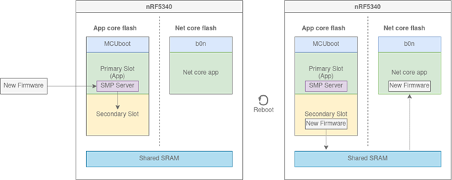
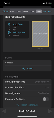
DFU OTA over BLE update of the Application Image using "app_update.bin" has worked for a long time & we have no problems with it. This works perfectly BOTH in nrf Connect for iOS well as in our own iOS application. Has worked reliably for more than 1 year now. 

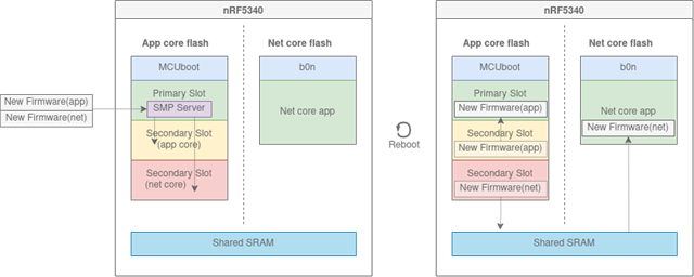
However, occasionally we need to do a "simultaneous" multi-image update of BOTH the Application & Network Cores.
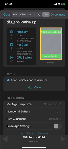
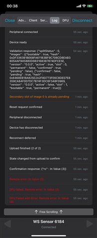
We can't get this to work & have tried many different configuration options. We always get the error "'Remote Error: In Value(3)" in nrfConnect Mobile on iOS (as well as in our own iOS application which includes DFU updates).  Have tried it numerous times with AND without the "Erase App Settings" switch set on (or off). The setting of the "Erase App Settings" seems to make no difference on the error returned.

I have read/studied the following:

https://developer.nordicsemi.com/nRF_Connect_SDK/doc/latest/nrf/working_with_nrf/nrf53/nrf5340.html#fota-updates 

and

https://github.com/hellesvik-nordic/samples_for_nrf_connect_sdk/tree/main/bootloader_samples/nrf5340

as well as read all the other related cases on devzone. But somehow I/we can't get it to work in our own firmware builds! So I must be missing or overlooked something fundamental!

Below are some screenshots from nrf Connect Mobile for iOS showing "success" when using "app_update_bin" but failure when using "DFU_application.zip". 
I have also included the log from nrf Connect for iOS when it fails with the multi-image update.

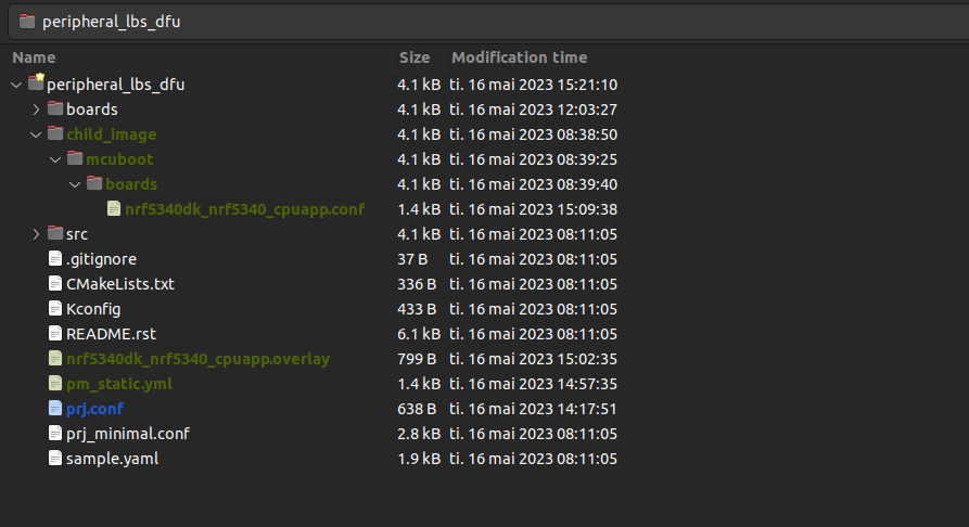
Below are copies of our prj.conf, hci_rpmsg.conf & mcuboot.conf

#
# Copyright (c) 2021 WearSense LLC
#

# WEARSENSE FIRMWARE REVISION TO BE UPDATED HERE!!!
CONFIG_BT_DIS_FW_REV_STR="09.21"

# CONFIG_WATCHDOG=y
CONFIG_REBOOT=y

# Activate Power Management (reduce power requirements
# see: https://devzone.nordicsemi.com/nordic/nordic-blog/b/blog/posts/optimizing-power-on-nrf53-designs
CONFIG_PM=y
CONFIG_PM_DEVICE=y
CONFIG_PM_DEVICE_RUNTIME=y
CONFIG_BOARD_ENABLE_DCDC_APP=y
CONFIG_BOARD_ENABLE_DCDC_NET=y
CONFIG_BOARD_ENABLE_DCDC_HV=y
CONFIG_SERIAL=n

# Errata 160 included in v2.3.0 - ensure System Clock is enabled
CONFIG_SYS_CLOCK_EXISTS=y

# to enable RTT logging (for debugging) - change next 2 lines to "=y"
# NOTE: set both "=n" for optimal power optimization (so disable for "production" or battery life/power monitor tests)
CONFIG_LOG=n
CONFIG_USE_SEGGER_RTT=n

CONFIG_RESET_ON_FATAL_ERROR=y   # not sure this works for non "Nordic DK" boards!?       
CONFIG_ASSERT=n    # crashes i2c init when turned on (=y) with RTT logging - need to investigate...!?

CONFIG_LOG_DEFAULT_LEVEL=3
# CONFIG_LOG_PROCESS_THREAD_STACK_SIZE=2048

# Debugging configuration
# CONFIG_THREAD_NAME=y
# CONFIG_THREAD_ANALYZER=y
# CONFIG_THREAD_ANALYZER_AUTO=y
# CONFIG_THREAD_ANALYZER_RUN_UNLOCKED=y
# CONFIG_THREAD_ANALYZER_USE_PRINTK=y

# CONFIG_ASSERT_VERBOSE=y
# CONFIG_ASSERT_NO_COND_INFO=n
# CONFIG_ASSERT_NO_MSG_INFO=n

# disable all things related to uarts, usb & console (for max power savings) - CONFIG_SERIAL=n already set above
CONFIG_CONSOLE=n
# CONFIG_STDOUT_CONSOLE=n
# CONFIG_USB_DEVICE_STACK=m
# CONFIG_TFM_LOG_LEVEL_SILENCE=y
# CONFIG_LOG_BACKEND_UART

# set stack & heap sizes.
CONFIG_HEAP_MEM_POOL_SIZE=8192
CONFIG_SYSTEM_WORKQUEUE_STACK_SIZE=8192
CONFIG_MAIN_STACK_SIZE=4096
CONFIG_BT_RX_STACK_SIZE=4096

# Disable the DK (nordic dev Boards) LED and Buttons library for WearSense boards
CONFIG_DK_LIBRARY=n

# required for generating random number for suffix of original BLE NAME set for device. 
CONFIG_ENTROPY_GENERATOR=y
CONFIG_ENTROPY_DEVICE_RANDOM_GENERATOR=y

# configure Settimgs to be stored in NVS Flash on nrf5340 SoC
CONFIG_FLASH=y
CONFIG_FLASH_PAGE_LAYOUT=y
CONFIG_FLASH_MAP=y
CONFIG_NVS=y
CONFIG_SETTINGS=y
CONFIG_SETTINGS_NVS=y
CONFIG_SETTINGS_RUNTIME=y

# BLE Settings
CONFIG_BT=y
CONFIG_BT_SETTINGS=n                        # for now we take care of our own BLE settings.
CONFIG_BT_CENTRAL=n
CONFIG_BT_PERIPHERAL=y
CONFIG_BT_DEVICE_NAME="WearSense Sensor"    # Name is re-defined & replaced at runtime
CONFIG_BT_DEVICE_NAME_DYNAMIC=y
CONFIG_BT_MAX_CONN=1
CONFIG_BT_MAX_PAIRED=1

# appearance 1344 = "Generic Sensor" 
# (see: https://specificationrefs.bluetooth.com/assigned-values/Appearance%20Values.pdf )
CONFIG_BT_DEVICE_APPEARANCE=1344

# configure BLE "Device Information Service" (BT_DIS) characteristics.
CONFIG_BT_DIS=y
CONFIG_BT_DIS_MODEL="WearSense LS2"
CONFIG_BT_DIS_MANUF="wear-sense.com"
CONFIG_BT_DIS_FW_REV=y
CONFIG_BT_DIS_SETTINGS=y            # allows following values to be assigned at runtime
CONFIG_BT_DIS_SERIAL_NUMBER=y       # assigned at runtime in code
CONFIG_BT_DIS_HW_REV=y              # assigned at runtime in code
CONFIG_BT_DIS_SW_REV=n              # not required for WearSense app. 
CONFIG_BT_DIS_PNP=n                 # not required for WearSense app.

CONFIG_BT_NUS=y         # Enable the NUS service (in advertising)

CONFIG_BT_BAS=y         # Enable the Battery Level service (in advertising)

CONFIG_BT_USER_DATA_LEN_UPDATE=y
#This is the maximum data length with Nordic Softdevice controller
CONFIG_BT_CTLR_DATA_LENGTH_MAX=251
#These buffers are needed for the data length max. 
CONFIG_BT_BUF_ACL_TX_SIZE=251
CONFIG_BT_BUF_ACL_RX_SIZE=251
#This is the maximum MTU size with Nordic Softdevice controller
CONFIG_BT_L2CAP_TX_MTU=247

CONFIG_BT_GAP_PERIPHERAL_PREF_PARAMS=y
CONFIG_BT_GAP_AUTO_UPDATE_CONN_PARAMS=y

# set BLE 'connect parameters' for lowest power consumption 
# so lower data transfer speed but low power when connected but not sending data... 
# 36 = 30ms, 48 = 60ms
# 30 = able to 'miss' max of 30 intervals of 60ms each to keep BLE connection alive.
# 600 = 6000 ms - max allowed by Apple (& probably others)
CONFIG_BT_PERIPHERAL_PREF_MIN_INT=36
CONFIG_BT_PERIPHERAL_PREF_MAX_INT=48    
CONFIG_BT_PERIPHERAL_PREF_LATENCY=30
CONFIG_BT_PERIPHERAL_PREF_TIMEOUT=600

CONFIG_NEWLIB_LIBC=y
CONFIG_NEWLIB_LIBC_FLOAT_PRINTF=y
CONFIG_NEWLIB_LIBC_FLOAT_SCANF=y

# Enable mcumgr (used for reset over BLE and OTA firmware updates).
CONFIG_MCUMGR=y

# Ensure an MCUboot-compatible binary is generated.
CONFIG_BOOTLOADER_MCUBOOT=y
CONFIG_MCUMGR_SMP_BT=y
CONFIG_MCUMGR_SMP_BT_AUTHEN=n
CONFIG_DFU_MULTI_IMAGE=y
CONFIG_DFU_MULTI_IMAGE_MAX_IMAGE_COUNT=2
CONFIG_NRF53_UPGRADE_NETWORK_CORE=y
CONFIG_MCUBOOT_IMG_MANAGER=y

# Enable core DFU/OTA features.
CONFIG_MCUMGR_CMD_IMG_MGMT=y
CONFIG_MCUMGR_CMD_OS_MGMT=y
CONFIG_NCS_SAMPLE_MCUMGR_BT_OTA_DFU=y

# set BLE 'Connect Interval' Parameters for SMP (used for OTA) to fastest possible transfer speed..
CONFIG_MCUMGR_SMP_BT_CONN_PARAM_CONTROL=y
CONFIG_MCUMGR_SMP_BT_CONN_PARAM_CONTROL_MIN_INT=12
CONFIG_MCUMGR_SMP_BT_CONN_PARAM_CONTROL_MAX_INT=12
CONFIG_MCUMGR_SMP_BT_CONN_PARAM_CONTROL_LATENCY=0
CONFIG_MCUMGR_SMP_BT_CONN_PARAM_CONTROL_TIMEOUT=200 

CONFIG_MCUMGR_SMP_WORKQUEUE_STACK_SIZE=8192
             
# Enable the SAADC ADC support
CONFIG_ADC=y
CONFIG_ADC_ASYNC=y
CONFIG_ADC_NRFX_SAADC=y

CONFIG_FPU=y

# I2C required to read Pressure Sensor & Accelerometer
CONFIG_I2C=y

#
# Copyright (c) 2021 Nordic Semiconductor ASA
#
# SPDX-License-Identifier: LicenseRef-Nordic-5-Clause
#

# required for max power savings!
CONFIG_LOG=n #changed
CONFIG_SERIAL=n
CONFIG_CONSOLE=n

CONFIG_IPC_SERVICE=y
# CONFIG_IPC_SERVICE_BACKEND_RPMSG=y
CONFIG_IPC_SERVICE_BACKEND_RPMSG_WQ_STACK_SIZE=4096
CONFIG_BT_RX_STACK_SIZE=4096

# BLE Settings
CONFIG_BT=y
# CONFIG_BT_SETTINGS=n      # for now we take care of our own BLE settings (no pairing, etc).
CONFIG_BT_CENTRAL=n
CONFIG_BT_PERIPHERAL=y
CONFIG_BT_HCI=y
CONFIG_BT_HCI_RAW=y
CONFIG_BT_MAX_CONN=2
CONFIG_BT_CTLR_ASSERT_HANDLER=n     # would like to set this to "y" & handle in application code. Checking with devzone!

#For data length update
CONFIG_BT_USER_DATA_LEN_UPDATE=y
#This is the maximum data length with Nordic Softdevice controller
CONFIG_BT_CTLR_DATA_LENGTH_MAX=251
#These buffers are needed for the data length max. 
CONFIG_BT_BUF_ACL_TX_SIZE=251
CONFIG_BT_BUF_ACL_RX_SIZE=251
#This is the maximum MTU size with Nordic Softdevice controller
CONFIG_BT_L2CAP_TX_MTU=247

# CONFIG_MCUBOOT_LOG_LEVEL_WRN=y
CONFIG_SERIAL=n
CONFIG_CONSOLE=n


Would really appreciate if you guys could have a quick look at this & let me know what I am missing!

Thanking you in anticipation

Best Regards

Gerard

Parents
  • Hi Gerard,

    I'm looking into reproducing the issue your issue, but in the meanwhile I am curious if you're able to get simultaneous DFU for the 5340 to work with any of the following tests

    1. The 5340 sample from the repository you linked?
    2. Test with any other sample known to work with DFU support such the smp sample with bluetooth (https://developer.nordicsemi.com/nRF_Connect_SDK/doc/latest/zephyr/samples/subsys/mgmt/mcumgr/smp_svr/README.html
    3. Try with an Android phone instead? If this is successful, then it is a bug in the iOS version of the application

    Let me know about the results and I'll get relay this to the relevant team(s) and consult closer with them

    Kind regards,
    Andreas

  • Hi Andreas

    Unfortunately I am traveling until Thursday - so don't have all my tools and/or devices handy to test 1 & 2 above. So will have to try that later.

    I had in fact tried it on Android and got the same error. As I originally tried it on a fairly old Android device, I just tried it again (an hour or two ago) on a recent Lenovo Tab M10 HD running Android 11 and the latest nrf Connect app for Android. Same problem.

    Below is a copy of the log from that Lenovo Android tablet (the DFU UI for the nrf Android App is definitely not as nice as the iOS app - it doesn't clearly show the result of the DFU update in the UI! - only the log shows the error)..

    nRF Connect, 2023-06-13
    Rev2 #6 (FC:A5:C3:35:34:F7)
    	19:26:12.961	gatt.close()
    D	19:26:12.962	wait(200)
    V	19:26:13.164	Connecting to FC:A5:C3:35:34:F7...
    D	19:26:13.164	gatt = device.connectGatt(autoConnect = false, TRANSPORT_LE, preferred PHY = LE 1M)
    D	19:26:14.297	[Callback] Connection state changed with status: 0 and new state: CONNECTED (2)
    I	19:26:14.297	Connected to FC:A5:C3:35:34:F7
    D	19:26:14.298	[Broadcast] Action received: android.bluetooth.device.action.ACL_CONNECTED
    V	19:26:14.331	Discovering services...
    D	19:26:14.357	gatt.discoverServices()
    I	19:26:14.697	Connection parameters updated (interval: 7.5ms, latency: 0, timeout: 5000ms)
    I	19:26:14.755	PHY updated (TX: LE 2M, RX: LE 2M)
    D	19:26:15.143	[Callback] Services discovered with status: 0
    I	19:26:15.144	Services discovered
    V	19:26:15.183	Generic Attribute (0x1801)
    - Service Changed [I] (0x2A05)
       Client Characteristic Configuration (0x2902)
    - Client Supported Features [R W] (0x2B29)
    - Database Hash [R] (0x2B2A)
    Generic Access (0x1800)
    - Device Name [R W] (0x2A00)
    - Appearance [R] (0x2A01)
    - Peripheral Preferred Connection Parameters [R] (0x2A04)
    Battery Service (0x180F)
    - Battery Level [N R] (0x2A19)
       Client Characteristic Configuration (0x2902)
    Device Information (0x180A)
    - Model Number String [R] (0x2A24)
    - Manufacturer Name String [R] (0x2A29)
    - Serial Number String [R] (0x2A25)
    - Firmware Revision String [R] (0x2A26)
    - Hardware Revision String [R] (0x2A27)
    Nordic UART Service (6e400001-b5a3-f393-e0a9-e50e24dcca9e)
    - TX Characteristic [N] (6e400003-b5a3-f393-e0a9-e50e24dcca9e)
       Client Characteristic Configuration (0x2902)
    - RX Characteristic [W WNR] (6e400002-b5a3-f393-e0a9-e50e24dcca9e)
    SMP Service (8d53dc1d-1db7-4cd3-868b-8a527460aa84)
    - SMP Characteristic [N WNR] (da2e7828-fbce-4e01-ae9e-261174997c48)
       Client Characteristic Configuration (0x2902)
    D	19:26:15.186	gatt.setCharacteristicNotification(00002a05-0000-1000-8000-00805f9b34fb, true)
    D	19:26:15.189	gatt.setCharacteristicNotification(00002a19-0000-1000-8000-00805f9b34fb, true)
    D	19:26:15.192	gatt.setCharacteristicNotification(6e400003-b5a3-f393-e0a9-e50e24dcca9e, true)
    I	19:26:15.254	Connection parameters updated (interval: 48.75ms, latency: 0, timeout: 5000ms)
    I	19:26:19.597	Connection parameters updated (interval: 52.5ms, latency: 30, timeout: 6000ms)
    V	19:32:58.513	[McuMgr] Connecting...
    D	19:32:58.532	[McuMgr] gatt = device.connectGatt(autoConnect = false, TRANSPORT_LE, LE 1M)
    D	19:32:58.610	[McuMgr] [Callback] Connection state changed with status: 0 and new state: 2 (CONNECTED)
    I	19:32:58.623	[McuMgr] Connected to FC:A5:C3:35:34:F7
    D	19:32:58.634	[McuMgr] wait(300)
    V	19:32:58.947	[McuMgr] Discovering services...
    D	19:32:58.961	[McuMgr] gatt.discoverServices()
    I	19:32:58.986	[McuMgr] Services discovered
    V	19:32:59.001	[McuMgr] Primary service found
    V	19:32:59.024	[McuMgr] Requesting new MTU...
    D	19:32:59.041	[McuMgr] gatt.requestMtu(498)
    I	19:32:59.858	[McuMgr] MTU changed to: 247
    D	19:32:59.878	[McuMgr] gatt.setCharacteristicNotification(da2e7828-fbce-4e01-ae9e-261174997c48, true)
    V	19:32:59.893	[McuMgr] Enabling notifications for da2e7828-fbce-4e01-ae9e-261174997c48
    D	19:32:59.907	[McuMgr] descriptor.setValue(0x01-00)
    D	19:32:59.921	[McuMgr] gatt.writeDescriptor(00002902-0000-1000-8000-00805f9b34fb)
    I	19:33:01.592	[McuMgr] Data written to descr. 00002902-0000-1000-8000-00805f9b34fb
    I	19:33:01.608	[McuMgr] Notifications enabled
    V	19:33:01.624	[McuMgr] Waiting for value change...
    V	19:33:01.638	[McuMgr] Writing characteristic da2e7828-fbce-4e01-ae9e-261174997c48 (WRITE COMMAND)
    D	19:33:01.654	[McuMgr] characteristic.setValue(0x000000010000FF06A0)
    D	19:33:01.668	[McuMgr] characteristic.setWriteType(WRITE COMMAND)
    D	19:33:01.684	[McuMgr] gatt.writeCharacteristic(da2e7828-fbce-4e01-ae9e-261174997c48)
    I	19:33:01.699	[McuMgr] Data written to da2e7828-fbce-4e01-ae9e-261174997c48
    W	19:33:02.638	[McuMgr] Request timed out
    A	19:33:02.660	[McuMgr] Sending (10 bytes) Header (Op: 0, Flags: 0, Len: 2, Group: 1, Seq: 0, Command: 0) CBOR {}
    V	19:33:02.676	[McuMgr] Writing characteristic da2e7828-fbce-4e01-ae9e-261174997c48 (WRITE COMMAND)
    D	19:33:02.693	[McuMgr] characteristic.setValue(0x0000000200010000BFFF)
    D	19:33:02.708	[McuMgr] characteristic.setWriteType(WRITE COMMAND)
    D	19:33:02.721	[McuMgr] gatt.writeCharacteristic(da2e7828-fbce-4e01-ae9e-261174997c48)
    I	19:33:02.803	[McuMgr] Data written to da2e7828-fbce-4e01-ae9e-261174997c48
    I	19:33:03.325	[McuMgr] Notification received from da2e7828-fbce-4e01-ae9e-261174997c48, value: (0x) 01-00-00-06-00-00-FF-06-BF-62-72-63-08-FF
    A	19:33:03.343	[McuMgr] Received Header (Op: 1, Flags: 0, Len: 6, Group: 0, Seq: 255, Command: 6) CBOR {"rc":8}
    W	19:33:03.360	[McuMgr] Error: NOT_SUPPORTED (8)
    I	19:33:03.484	[McuMgr] Notification received from da2e7828-fbce-4e01-ae9e-261174997c48, value: (0x) 01-00-00-F4-00-01-00-00-BF-66-69-6D-61-67-65-73-9F-BF-64-73-6C-6F-74-00-67-76-65-72-73-69-6F-6E-65-30-2E-30-2E-30-64-68-61-73-68-58-20-6E-63-66-05-46-FC-33-A5-5E-35-85-CC-EC-20-91-D1-71-C2-4F-D1-A8-BA-45-1E-96-9B-7B-B9-6A-30-F0-19-68-62-6F-6F-74-61-62-6C-65-F5-67-70-65-6E-64-69-6E-67-F4-69-63-6F-6E-66-69-72-6D-65-64-F5-66-61-63-74-69-76-65-F5-69-70-65-72-6D-61-6E-65-6E-74-F4-FF-BF-64-73-6C-6F-74-01-67-76-65-72-73-69-6F-6E-65-30-2E-30-2E-30-64-68-61-73-68-58-20-9D-E6-5E-67-CB-B0-0E-A5-92-09-82-3D-D6-7E-DF-29-FF-AA-23-F9-C3-CE-0F-FC-E3-81-3A-03-C5-A2-FE-BD-68-62-6F-6F-74-61-62-6C-65-F5-67-70-65-6E-64-69-6E-67-F4-69-63-6F-6E-66-69-72-6D-65-64-F4-66-61-63-74-69-76-65-F4-69-70-65-72-6D-61-6E-65-6E-74-F4-FF-FF-6B-73-70-6C-69-74
    I	19:33:03.599	[McuMgr] Notification received from da2e7828-fbce-4e01-ae9e-261174997c48, value: (0x) 53-74-61-74-75-73-00-FF
    A	19:33:03.617	[McuMgr] Received Header (Op: 1, Flags: 0, Len: 244, Group: 1, Seq: 0, Command: 0) CBOR {"images":[{"slot":0,"version":"0.0.0","hash":"bmNmBUb8M6VeNYXM7CCR0XHCT9GoukUelpt7uWow8Bk=","bootable":true,"pending":false,"confirmed":true,"active":true,"permanent":false},{"slot":1,"version":"0.0.0","hash":"neZeZ8uwDqWSCYI91n7fKf+qI/nDzg/844E6A8Wi/r0=","bootable":true,"pending":false,"confirmed":false,"active":false,"permanent":false}],"splitStatus":0}
    V	19:33:03.652	[McuMgr] Uploading firmware...
    I	19:33:13.253	Connection parameters updated (interval: 15.0ms, latency: 0, timeout: 2000ms)
    A	19:33:42.548	[McuMgr] 175347 bytes sent in 34969 ms (5.01 kB/s)
    A	19:34:12.929	[McuMgr] 144610 bytes sent in 27111 ms (5.33 kB/s)
    A	19:34:12.971	[McuMgr] Sending (10 bytes) Header (Op: 2, Flags: 0, Len: 2, Group: 63, Seq: 186, Command: 0) CBOR {}
    V	19:34:12.987	[McuMgr] Writing characteristic da2e7828-fbce-4e01-ae9e-261174997c48 (WRITE COMMAND)
    D	19:34:13.003	[McuMgr] characteristic.setValue(0x02000002003FBA00BFFF)
    D	19:34:13.017	[McuMgr] characteristic.setWriteType(WRITE COMMAND)
    D	19:34:13.033	[McuMgr] gatt.writeCharacteristic(da2e7828-fbce-4e01-ae9e-261174997c48)
    I	19:34:13.051	[McuMgr] Data written to da2e7828-fbce-4e01-ae9e-261174997c48
    I	19:34:13.186	[McuMgr] Notification received from da2e7828-fbce-4e01-ae9e-261174997c48, value: (0x) 03-00-00-06-00-3F-BA-00-BF-62-72-63-08-FF
    A	19:34:13.202	[McuMgr] Received Header (Op: 3, Flags: 0, Len: 6, Group: 63, Seq: 186, Command: 0) CBOR {"rc":8}
    W	19:34:13.220	[McuMgr] Error: NOT_SUPPORTED (8)
    V	19:34:13.250	[McuMgr] New state: CONFIRM
    A	19:34:13.269	[McuMgr] Sending (58 bytes) Header (Op: 2, Flags: 0, Len: 50, Group: 1, Seq: 187, Command: 0) CBOR {"confirm":true,"hash":"neZeZ8uwDqWSCYI91n7fKf+qI/nDzg/844E6A8Wi/r0="}
    V	19:34:13.283	[McuMgr] Writing characteristic da2e7828-fbce-4e01-ae9e-261174997c48 (WRITE COMMAND)
    D	19:34:13.300	[McuMgr] characteristic.setValue(0x020000320001BB00BF67636F6E6669726DF5646861736858209DE65E67CBB00EA59209823DD67EDF29FFAA23F9C3CE0FFCE3813A03C5A2FEBDFF)
    D	19:34:13.315	[McuMgr] characteristic.setWriteType(WRITE COMMAND)
    D	19:34:13.331	[McuMgr] gatt.writeCharacteristic(da2e7828-fbce-4e01-ae9e-261174997c48)
    I	19:34:13.367	[McuMgr] Data written to da2e7828-fbce-4e01-ae9e-261174997c48
    I	19:34:13.387	[McuMgr] Notification received from da2e7828-fbce-4e01-ae9e-261174997c48, value: (0x) 03-00-00-F4-00-01-BB-00-BF-66-69-6D-61-67-65-73-9F-BF-64-73-6C-6F-74-00-67-76-65-72-73-69-6F-6E-65-30-2E-30-2E-30-64-68-61-73-68-58-20-6E-63-66-05-46-FC-33-A5-5E-35-85-CC-EC-20-91-D1-71-C2-4F-D1-A8-BA-45-1E-96-9B-7B-B9-6A-30-F0-19-68-62-6F-6F-74-61-62-6C-65-F5-67-70-65-6E-64-69-6E-67-F4-69-63-6F-6E-66-69-72-6D-65-64-F5-66-61-63-74-69-76-65-F5-69-70-65-72-6D-61-6E-65-6E-74-F4-FF-BF-64-73-6C-6F-74-01-67-76-65-72-73-69-6F-6E-65-30-2E-30-2E-30-64-68-61-73-68-58-20-9D-E6-5E-67-CB-B0-0E-A5-92-09-82-3D-D6-7E-DF-29-FF-AA-23-F9-C3-CE-0F-FC-E3-81-3A-03-C5-A2-FE-BD-68-62-6F-6F-74-61-62-6C-65-F5-67-70-65-6E-64-69-6E-67-F5-69-63-6F-6E-66-69-72-6D-65-64-F4-66-61-63-74-69-76-65-F4-69-70-65-72-6D-61-6E-65-6E-74-F5-FF-FF-6B-73-70-6C-69-74
    I	19:34:13.550	[McuMgr] Notification received from da2e7828-fbce-4e01-ae9e-261174997c48, value: (0x) 53-74-61-74-75-73-00-FF
    A	19:34:13.570	[McuMgr] Received Header (Op: 3, Flags: 0, Len: 244, Group: 1, Seq: 187, Command: 0) CBOR {"images":[{"slot":0,"version":"0.0.0","hash":"bmNmBUb8M6VeNYXM7CCR0XHCT9GoukUelpt7uWow8Bk=","bootable":true,"pending":false,"confirmed":true,"active":true,"permanent":false},{"slot":1,"version":"0.0.0","hash":"neZeZ8uwDqWSCYI91n7fKf+qI/nDzg/844E6A8Wi/r0=","bootable":true,"pending":true,"confirmed":false,"active":false,"permanent":true}],"splitStatus":0}
    A	19:34:13.594	[McuMgr] Sending (58 bytes) Header (Op: 2, Flags: 0, Len: 50, Group: 1, Seq: 188, Command: 0) CBOR {"confirm":true,"hash":"xhM+D4xfppfMoSthxdXuZU3MILMoVJ4t8XuBgpQYgb4="}
    V	19:34:13.612	[McuMgr] Writing characteristic da2e7828-fbce-4e01-ae9e-261174997c48 (WRITE COMMAND)
    D	19:34:13.626	[McuMgr] characteristic.setValue(0x020000320001BC00BF67636F6E6669726DF564686173685820C6133E0F8C5FA697CCA12B61C5D5EE654DCC20B328549E2DF17B8182941881BEFF)
    D	19:34:13.641	[McuMgr] characteristic.setWriteType(WRITE COMMAND)
    D	19:34:13.656	[McuMgr] gatt.writeCharacteristic(da2e7828-fbce-4e01-ae9e-261174997c48)
    I	19:34:13.675	[McuMgr] Data written to da2e7828-fbce-4e01-ae9e-261174997c48
    I	19:34:13.697	[McuMgr] Notification received from da2e7828-fbce-4e01-ae9e-261174997c48, value: (0x) 03-00-00-06-00-01-BC-00-BF-62-72-63-03-FF
    A	19:34:13.719	[McuMgr] Received Header (Op: 3, Flags: 0, Len: 6, Group: 1, Seq: 188, Command: 0) CBOR {"rc":3}
    W	19:34:13.733	[McuMgr] Error: IN_VALUE (3)
    V	19:34:13.908	[McuMgr] Disconnecting...
    D	19:34:13.925	[McuMgr] gatt.disconnect()
    D	19:34:13.947	[McuMgr] [Callback] Connection state changed with status: 0 and new state: 0 (DISCONNECTED)
    I	19:34:13.962	[McuMgr] Disconnected
    D	19:34:13.980	[McuMgr] gatt.close()
    I	19:34:18.900	Connection parameters updated (interval: 52.5ms, latency: 30, timeout: 6000ms)
    

    Note line 114, which reads:

    19:34:13.733 [McuMgr] Error: IN_VALUE (3)

    Note that although my original post showed the tests & screenshot for the nrf iOS Connect app, I also tested this using our own iOS app which uses the IOS-nRF-Connect-Device-Manager library (https://github.com/NordicSemiconductor/IOS-nRF-Connect-Device-Manager) - which is probably the same library used by the nrf Connect for iOS app! :) 
    Anyway, I get the same error code when I try using the iOS library as I get in the nrf Connect Mobile apps (for iOS and Android). So the error seems consistent across three different "platforms"!

    Also tried it with numerous different CONFIG options but nothing I do seems to make any difference & I always get the same error - yet updating ONLY the "Application Core" works like a charm (on all 3 "platforms") & has worked for more than 1 year as I mentioned.

    This is really frustrating as you can imagine....

    Hope you can help me resolve this issue as it is holding up our progress to upgrade a number of units already in the field.

    Thanks!

    Gerard

  • Hi Gerard,

    I do understand the frustration you're feeling and doing our best in finding a solution for you.

    I've reread your issue after posting my first comment last week and I saw that a requirement was to do simultanous DFU without external flash. This is not something that we have any existing samples for for the nRF5340, so I had to do some digging around. Fortunately I found an unofficial sample showcasing how to do this created by a colleague of mine.

    I don't think we're quite out of the woods yet, as you mention you have devices in the field, as adding the simultaneous DFU support without external flash might require some changes to your code. But just so we have it clear, could you verify if you have had simultaneous DFU without external flash working at any point in time, or has any firmware update you've been doing been non-simultaneous prior to this? (Edit: I see that you've stated that non-simultaneous with only the app-core has been working, but a verification is good nonetheless)

    GerardB said:
    Anyway, I get the same error code when I try using the iOS library as I get in the nrf Connect Mobile apps (for iOS and Android). So the error seems consistent across three different "platforms"!

    "Good" to have that verification! If the sample below does not fix the issue, I will continue pushing this to the mobile apps team and discuss with them if this can be fixed in the application, but most likely the supplied sample should solve it. I suggest you try that first out of the box with the nRF Connect Mobile apps

    Below follows some comments from my colleague Vidar regarding what he had done to make this work in his sample:

    My example is based on the Peripheral LBS sample from SDK 2.3.0 and should support simultaneous multi-image dfu support over BLE (I did a quick test where I successfully updated the app+netcore image).

    File/directory names highlighted in green have been added, and prj.conf in blue has been modified.

    Kconfig settings added to prj.conf:

    diff --git a/prj.conf b/prj.conf
    index 63a6818..e314ca7 100644
    --- a/prj.conf
    +++ b/prj.conf
    @@ -14,4 +14,14 @@ CONFIG_BT_LBS=y
     CONFIG_BT_LBS_POLL_BUTTON=y
     CONFIG_DK_LIBRARY=y
     
    -CONFIG_SYSTEM_WORKQUEUE_STACK_SIZE=2048
    +CONFIG_BOOTLOADER_MCUBOOT=y
    +CONFIG_MCUBOOT_USE_ALL_AVAILABLE_RAM=y
    +CONFIG_NCS_SAMPLE_MCUMGR_BT_OTA_DFU=y
    +CONFIG_NCS_SAMPLE_MCUMGR_BT_OTA_DFU_SPEEDUP=y
    +CONFIG_MCUBOOT_IMAGE_VERSION="2.3.0+0"
    +CONFIG_NRF53_UPGRADE_NETWORK_CORE=y
    +CONFIG_UPDATEABLE_IMAGE_NUMBER=2
    +CONFIG_ADD_MCUBOOT_MEDIATE_SIM_FLASH_DTS=y
    +
    +
    +CONFIG_SYSTEM_WORKQUEUE_STACK_SIZE=4096

    Memory partition layout after adding static partition file (pm_static.yml):

    Project

    Edit: Reuploaded zip file

    8306.peripheral_lbs_dfu.zip

  • Hi again Andreas,

    Thanks for your fast response - MUCH appreciated!!

    I will definitely try your suggested solution on Thursday as I am traveling right now. Will let you know what I find.

    Quick comment/questions:

    1. No External Flash - You wrote:

    " I saw that a requirement was to do simultanous DFU without external flash. This is not something that we have any existing samples for for the nRF5340, so I had to do some digging around."

    I just want to make sure we are using the same terminology :). By "no external flash" I mean that the only flash that exists on our 5340 based board is the 1MB of flash integrated in the 5340 SoC itself. I would have thought this is typical but from what you say the "standard" DFU over BLE examples assume that additional (external) flash is required. I am sort of surprised to hear that the examples would not be based on using ONLY the integrated 1MB flash inherent in the 5340 SoC. Is that because on the other (older) nrf products (like the nrf52 & nrf52), there is only a single core to update - which was historically all that was required/needed? I am just curious to better understand why the "standard" recommended way (in the examples) would not "encourage" one to "simply" use the internal 5340 flash only? Can you maybe clarify this a little for me (purely for me to better understand the historical context of this as I want to make sure I am on the right track here! :) ).  

    2. Confirm: Our existing DFU ONLY updates the application Core Image. You wrote:

    "But just so we have it clear, could you verify if you have had simultaneous DFU without external flash working at any point in time, or has any firmware update you've been doing been non-simultaneous prior to this?"

    So until now ALL our DFU OTA (via BLE) have ONLY updated the Application core. This has always worked extremely well & has served us well! I guess we were "lucky" in that we never needed to update the Network Core until now. The reason for this is (I ASSUME!?) that until now our firmware in all our field & test units have been developed using the nrf Connect SDK v1.9.1. However a few months ago we moved all our development over to SDK v2.3.0. The result of this was that AFTER moving to SDK v2.3.0, we found that when we do an DFU OTA update of the Application Core ONLY (as we always did!), the device will no longer work (continuous reset loop). It took me/us a while to conclude (!?) that this is probably due to the fact that the new Application Image (developed with SDK v2.3.0) is no longer "compatible" with the already installed Network Core (which was originally built using SDK v1.9.1). I am still not 100% sure that this assumption of mine is correct!? :) Would REALLY appreciate it if you could actually confirm that!?  

    So I am still assuming that when one changes major SDK versions (eg: from SDK v1.9.1 to v2.3.0), DFU updates MUST update BOTH Cores "simultaneously" -  to ensure the firmware in both cores remain "compatible" with each other. Is that correct?  So it seems we have no choice but to figure out how to do a so-called "simultaneous" DFU update of both cores. Does my reasoning makes sense so far!?

    Even if this is a problem for existing field units (we'll figure out how to resolve that on our end!), I just want to make sure that my "logic/reasoning" as to why we now need to do a "simultaneous" DFU update (of both cores) is correct? Can you please comment on whether or not I have understood all this correctly!?

    3. I have a nrf5340DK board as well. I was under the impression that it also has no "external flash". Which means that the previous DFU "simultaneous update" examples would not work on (or were not designed for) the nrf5340Dk board without adding additional flash via the expansion connectors. Right? 

    Thanks again for you super support in all this - duly impressed! :) 

    Regards

    Gerard

  • Hi,

    GerardB said:
    Thanks for your fast response - MUCH appreciated!!

    I will definitely try your suggested solution on Thursday as I am traveling right now. Will let you know what I find.

    Glad to hear that, we're happy to help! 

    GerardB said:
    1. No External Flash - You wrote:

    I will answer this item by breaking it up into the sub-questions you mention and the whole part sums up the entire answer

    GerardB said:
    I just want to make sure we are using the same terminology :). By "no external flash" I mean that the only flash that exists on our 5340 based board is the 1MB of flash integrated in the 5340 SoC itself.

    Yes, this is the same terminology we're using. When we're talking about an external flash, we typically talk about a 64MB external SPI NOR flash that you can find on for instance our nRF52840DKs and nRF5340DKs in additional to the 1MB "internal" flash that corresponds to the flash that you mention.

    GerardB said:
    . I would have thought this is typical but from what you say the "standard" DFU over BLE examples assume that additional (external) flash is required. I am sort of surprised to hear that the examples would not be based on using ONLY the integrated 1MB flash inherent in the 5340 SoC. Is that because on the other (older) nrf products (like the nrf52 & nrf52), there is only a single core to update - which was historically all that was required/needed?

    I might have been a bit hard on the jumping to using "required", as that is not the complete truth. To clarify: it is not required, but the implementations we have in the samples using simultaneous DFU for both cores of the nRF5340 uses the external flash due to allowing for a larger application.

    What is required when performing simultaneous DFU is to have two secondary slots available, one for the app core and one for the net core. This further emphasizes the motivation for external flash: Having two secondary slots reduces the available flash you can allocate to the bootloader and primary application slot (where the application is running for) leading to ROM limitations for your application. 

    The images below is from https://github.com/hellesvik-nordic/samples_for_nrf_connect_sdk/tree/main/bootloader_samples/nrf5340, which is a repository containing some unofficial samples showcasing how to do various DFU methods, showcases the DFU flow. The theory behind it is motivated by the simultaneous multi-image DFU documentation among others. The sample in the repo is only supported up to NCS v2.2.0, but here is a version of the sample (with external flash) that is supported in v2.3.0

    7651.mcuboot_smp_ble_simultaneous_2_3_0.zip

    Simultaneous:


    Non-simultaneous (the one you've been using for updating your application)
     

    For instance by compiling https://github.com/hellesvik-nordic/samples_for_nrf_connect_sdk/tree/main/bootloader_samples/nrf5340/mcuboot_smp_ble_simultaneous, which uses the external flash for the two secondary slots has the following partition layout. Compare it to the one in Vidars sample in my previous reply and you'll see the difference with regards to where the two mcuboot secondary partitions are located and how much available flash you can allocate to the primary application slot:

     C:/Nordic/SDKs/ncs/my_projects/2.2.0/mcuboot_smp_ble_simultaneous/build/hci_rpmsg/partitions_CPUNET.yml"  external_flash (0x800000 - 8192kB):
    +------------------------------------------------+
    | 0x0: mcuboot_secondary (0xf4000 - 976kB)       |
    | 0xf4000: mcuboot_secondary_1 (0x40000 - 256kB) |
    | 0x134000: external_flash (0x6cc000 - 6960kB)   |
    +------------------------------------------------+
    
      flash_primary (0x100000 - 1024kB):
    +-------------------------------------------------+
    | 0x0: mcuboot (0xc000 - 48kB)                    |
    +---0xc000: mcuboot_primary (0xf4000 - 976kB)-----+
    | 0xc000: mcuboot_pad (0x200 - 512B)              |
    +---0xc200: mcuboot_primary_app (0xf3e00 - 975kB)-+
    | 0xc200: app (0xf3e00 - 975kB)                   |
    +-------------------------------------------------+
    
      otp (0x2fc - 764B):
    +------------------------------+
    | 0xff8100: otp (0x2fc - 764B) |
    +------------------------------+
    
      ram_flash (0x40000 - 256kB):
    +------------------------------------------+
    | 0x0: mcuboot_primary_1 (0x40000 - 256kB) |
    | 0x40000: ram_flash (0x0 - 0B)            |
    +------------------------------------------+
    
      sram_primary (0x80000 - 512kB):
    +-----------------------------------------------+
    | 0x20000000: pcd_sram (0x2000 - 8kB)           |
    | 0x20002000: sram_primary (0x6e000 - 440kB)    |
    | 0x20070000: rpmsg_nrf53_sram (0x10000 - 64kB) |
    +-----------------------------------------------+
    
     CPUNET flash_primary (0x40000 - 256kB):
    +--------------------------------------------+
    +---0x1000000: b0n_container (0x8800 - 34kB)-+
    | 0x1000000: b0n (0x8580 - 33kB)             |
    | 0x1008580: provision (0x280 - 640B)        |
    +---0x1008800: app (0x37800 - 222kB)---------+
    | 0x1008800: hci_rpmsg (0x37800 - 222kB)     |
    +--------------------------------------------+
    
     CPUNET sram_primary (0x10000 - 64kB):
    +-------------------------------------------+
    | 0x21000000: sram_primary (0x10000 - 64kB) |
    +-------------------------------------------+
    

    The difference for simultaneous with external flash left for your application is roughly*: 1MB - bootloader = available flash for application (since everything else is on the external flash)

    The difference for simultaneous  without external flash is roughly: 1MB - bootloader - the application size - the netcore size = available flash for the application

    The difference for non-simultaneous without external flash is roughly: 1MB - bootloader - application size = available flash for the application

    * not including padding, aligns and in case you have an immutable bootloader + more.

    GerardB said:
    Is that because on the other (older) nrf products (like the nrf52 & nrf52), there is only a single core to update - which was historically all that was required/needed?

    In a way, yes. As the previous section mentions the external flash is recommended due to the amount of flash you will be required for the update images, and you could say that historically the 52- and 51 series only required the internal flash. But the more precise way to formulate it with the historical analogy is that historically applications rarely (take the 'rarely' with a pinch of salt) exceeded roughly half of the available flash on the SoC. For instance the nRF52840 with 1 core and 1MB flash has not met too much resistance w.r.t adding DFU support before many applications started having multiple communication protocols

    GerardB said:
    I am just curious to better understand why the "standard" recommended way (in the examples) would not "encourage" one to "simply" use the internal 5340 flash only?

    So to summarize your first section of question it all comes down to flash size limitations and the flash size growth of embedded applications. Having an external flash available for allocating the secondary application slot(s) frees up more flash on the internal flash for the application which then allows developers to create more complex applications. There are certainly other aspects that I have not thought of mentioning here, but this is the key item that I consider the motivation for using external flash for firmware update partitions.

    GerardB said:
    2. Confirm: Our existing DFU ONLY updates the application Core Image. You wrote:

    I will go through the second item in similar terms as the first one

    GerardB said:
    So until now ALL our DFU OTA (via BLE) have ONLY updated the Application core. This has always worked extremely well & has served us well! I guess we were "lucky" in that we never needed to update the Network Core until now. The reason for this is (I ASSUME!?) that until now our firmware in all our field & test units have been developed using the nrf Connect SDK v1.9.1

    Noted, that clarifies the question I had regarding which type of DFU you had been doing prior to this. It might have been the case that you were lucky, but in short terms you should not be needed to update the netcore unless the hci interface is updated.

    GerardB said:
    However a few months ago we moved all our development over to SDK v2.3.0. The result of this was that AFTER moving to SDK v2.3.0, we found that when we do an DFU OTA update of the Application Core ONLY (as we always did!), the device will no longer work (continuous reset loop). It took me/us a while to conclude (!?) that this is probably due to the fact that the new Application Image (developed with SDK v2.3.0) is no longer "compatible" with the already installed Network Core (which was originally built using SDK v1.9.1). I am still not 100% sure that this assumption of mine is correct!? :) Would REALLY appreciate it if you could actually confirm that!?

    which leads us to this. As I mentioned there has most likely been changes in the hci interface in between these versions which causes the cores not being able to communicate with each other leading to the infinite reset loop.

    GerardB said:
    So I am still assuming that when one changes major SDK versions (eg: from SDK v1.9.1 to v2.3.0), DFU updates MUST update BOTH Cores "simultaneously" -  to ensure the firmware in both cores remain "compatible" with each other. Is that correct?  So it seems we have no choice but to figure out how to do a so-called "simultaneous" DFU update of both cores. Does my reasoning makes sense so far!?

    Your reasoning makes perfect sense. 

    What you've done so far is to do a non-simultaneous update of only the application core, which is a perfectly valid method for updating both cores (in the correct sequence) as long as the interface between the cores is not updated. This method does also work for updating the netcore in the correct sequence with the appcore given the previous condition regarding changes in the hci interface has not been met. Which is also why your app updates using NCS v1.9.1 has worked without issues. But when migrating 4 major releases from v1.9.x to v.2.3.x I suspect there has been changes in the interface between the cores which is large enough to break the application and putting it in the infinite reset loop. 

    In such a case, you will be required to update both cores at the same time, as updating one at the time will not be possible due to what you have unfortunately observed.

    A slight disclaimer here: I can't 100% conclude without digging into logs and debug properly if it is the changes in the major releases that has caused a discrepancy in your firmware that causes the infinite restart loop, but I strongly suspect it. 

    GerardB said:
    Even if this is a problem for existing field units (we'll figure out how to resolve that on our end!), I just want to make sure that my "logic/reasoning" as to why we now need to do a "simultaneous" DFU update (of both cores) is correct? Can you please comment on whether or not I have understood all this correctly!?

    I agree with your reasoning and I do believe that you will be able to solve this issue. You are definitely on the right track

    Please let me know if the explanation makes sense and feel free to ask follow up questions if you want me to clarify anything!

    Kind regards,
    Andreas

  • Hi again Andreas,

    WOW - what an answer - perfect - you are REALLY a good "teacher"! Thanks for taking so much of your time to CLEARLY explain all the key details for me - much appreciated!

    I feel I finally understand the issues involved and how (& why!) it all works now. Super interesting - I should have realized a lot of these things before but guess I never stopped long enough to think about it.

    The example you included (from Vidar) builds with no problem - so will test it out as soon as my computer & my 5340DK board are in the same place - probably by tomorrow morning.

    A couple of follow-up comments/questions:

    1. In Vidar's "pm_static.yml" file he defines an "otp" partition. This is not clear to me - can you maybe explain the purpose of that partition?

    otp:

    address: 0xff8100

    end_address: 0xff83fc

    region: otp

    size: 0x2fc

    2. Also in the "Memory partition layout after adding static partition file (pm_static.yml):" (image) you included earlier, it still shows a small "external flash" partition. As the example is supposedly demonstrating how to do a simultaneous update of both images without using any external flash, I am a little unclear as to why that partition is there?

    Edit: Never mind - I get it now & see his special overlay file where he defines it...!

    3. Changes in the hci interface.
    As you explained so well (and as I suspected!), obviously this is the key to when one needs to do a 
    simultaneous update of both images. What still confuses me is how one determines (programmatically!?) whether or not the hci interface (ie: the SoftController version & its interface) has in fact changed so that in that case we can initiate a simultaneous update of both images (vs. updating only the Application Core image)? Is there any relatively simple way to determine this?

    EDIT: end of travels - have my development system/tools up & running again.... 

    4. OK - I successfully ran the Vidar example on my 5340DK board and and managed to do multi-image updates on it - progress.. :)

    I then modified the various config files on our own (more complex) firmware & added the same static partition file to try & achieve the functionality of Vidar's example.  After resolving a few build issues, I managed to successfully run that on our own custom 5340 board!!. It seems to work & I can now successfully do a simultaneous multi-image update (using nrf Connect on iOS) between Vidar's example and our own code (starting with a J-link flash of Vidar's example). Tried it a few times to swap between them & all seems to work well - WOW! :) 

    I obviously need to do more testing but what I did notice is that I can't update directly from our own "old" firmware (with our original partitioning / mcuboot) to the new version (with the Vidar-like partitioning & mcuboot) - or vice versa (updates are signaled as successful but device fails to reboot properly & is no longer connectable in that case). I assume this means that the partition layout between the "old" and the "new" versions need to be the same but I am not sure about that - so maybe you can give me some clarity on that, ie: is this what you would expect?

    We can probably live with that but it would be useful if we could DFU over BLE in almost the same way that we can reflash completely with J-link (eg: move from the v1.9.1 built versions to the new v2.3.0 version & vice versa)! But I have a feeling that may not be possible (unless the partition layout is the same between all versions)!? 

    5. Looking at Vidar's (& now mine!) partition map, it seems we will be able to grow our app up to roughly 343.5kB. Right now our app is around 175kB (without logging) - so it looks like we have enough "room" to grow. Am I interpreting that correctly?

    Thanks again for all you help so far.

    Best Regards

    Gerard

  • Hi Gerard,

    I've been out of office since Thursday last week and I saw your reply just now. Thank you for the kind words, they are appreciated! 

    GerardB said:
    1. In Vidar's "pm_static.yml" file he defines an "otp" partition. This is not clear to me - can you maybe explain the purpose of that partition?

    I think the 'formal answer' is the best answer in this case, and that one can be seen in 7.17.1 to 7.17.4 in the PS (https://infocenter.nordicsemi.com/pdf/nRF5340_PS_v1.3.pdf) where it in 7.17.4.1 is stated that the OTP is a region of the UICR that contains a user defined static configuration of the device, which is then included by the default, dynamic partitioning scheme which is called upon when you build an application for the nRF5340

    Edit: On the nRF5340 (and 9160) this is an emulated OTP, so it is not a true OTP. It can be written again after a full erase of the SoC.

    I can also add that the OTP is not readprotected, so anything can read it and it is typically used for values that should be written once and never changed in the product lifetime, such as User ID or non-reversible activation of features.

    GerardB said:
    2. Also in the "Memory partition layout after adding static partition file (pm_static.yml):" (image) you included earlier, it still shows a small "external flash" partition. As the example is supposedly demonstrating how to do a simultaneous update of both images without using any external flash, I am a little unclear as to why that partition is there?

    The external flash partition of 8MB shows up in the samples due it being being built for the nRF5340DK. Both this DK and the nRF52840DK has the mx25r64 enabled which is why it shows up.

    As you can see in the image you mention, this partition is not used for anything other than storage and is not used to store any of the app-images during the DFU process. You should be able to change and/or disable it in the app.overlay if needed

    GerardB said:
    3. Changes in the hci interface.

    I'm not sure if I can come up with a suggestion that fits all cases regarding how to check if the interface has been updated, but in general we recommend to go through the release notes for every version you intend to migrate up. 

    In addition, the safest thing to say is that if you migrate your application to a different version, we recommend that you update both cores and that you use a static partition. In theory it may not be necessary to update both cores between each version you migrate, but it is definitely the safest solution.

    We also have this migration note for NCS v2.0.0, as this is an update where a lot of changes happened https://developer.nordicsemi.com/nRF_Connect_SDK/doc/latest/nrf/migration/migration_guide_1.x_to_2.x.html. Some items here may be relevant when following the procedure you've just done in your project, but I don't see anything specifically mentioning changes in the firmware running on the network core. 

    GerardB said:
    I then modified the various config files on our own (more complex) firmware & added the same static partition file to try & achieve the functionality of Vidar's example.  After resolving a few build issues, I managed to successfully run that on our own custom 5340 board!!. It seems to work & I can now successfully do a simultaneous multi-image update (using nrf Connect on iOS) between Vidar's example and our own code (starting with a J-link flash of Vidar's example). Tried it a few times to swap between them & all seems to work well - WOW! :) 

    So happy to hear that it worked without too much hassle! 

    GerardB said:
    I obviously need to do more testing but what I did notice is that I can't update directly from our own "old" firmware (with our original partitioning / mcuboot) to the new version (with the Vidar-like partitioning & mcuboot) - or vice versa (updates are signaled as successful but device fails to reboot properly & is no longer connectable in that case). I assume this means that the partition layout between the "old" and the "new" versions need to be the same but I am not sure about that - so maybe you can give me some clarity on that, ie: is this what you would expect?

    Yes, your observation is once again 100% correct. As I previously mentioned in this reply, you need to use a static partition when migrating between versions. Using the default, dynamic method, you may risk that the new build has slight changes from the original firmware, which typically leads to issues such as the bootloader not knowing where the app image starts and similar issues.

    See static configuration found in https://developer.nordicsemi.com/nRF_Connect_SDK/doc/latest/nrf/scripts/partition_manager/partition_manager.html

    GerardB said:
    We can probably live with that but it would be useful if we could DFU over BLE in almost the same way that we can reflash completely with J-link (eg: move from the v1.9.1 built versions to the new v2.3.0 version & vice versa)! But I have a feeling that may not be possible (unless the partition layout is the same between all versions)!? 

    It can be done DFU over BLE in the same way as previously, but it requires you, as you state, to have the same partition between all version. Typically this is done by using the same partitioning as you have in your original firmware (v1.9.1) and add that to the static yml file before building the new firmware. 

    GerardB said:
    5. Looking at Vidar's (& now mine!) partition map, it seems we will be able to grow our app up to roughly 343.5kB. Right now our app is around 175kB (without logging) - so it looks like we have enough "room" to grow. Am I interpreting that correctly?

    Yes, this is correct. As long as no other partition on the flash_primary partition increases in size and thus increases their share of the available internal flash, you should be able to support an application that is 343.5kB

    PS: One thing that I just discussed with a colleague regarding the existing, updated units you had in field is that if you have serial recovery enabled in mcuboot, you should be able to recover the images by sending someone to update them physically through USB (given that you have that peripheral on your devices).

    If you don't have serial recovery, you could for instance add that to the new version of the firmware you will be building. It should not require too much ROM. And if you haven't optimized your mcuboot yet, you might even be able to fit serial recovery without increasing the partition size and instead optimize features that are not needed. The nRF Machine Learning sample showcases how to optimize Mcuboot very nicely developer.nordicsemi.com/.../README.html

    Let me know if this clarifies things for you, and please feel free to dig more if I have been too vague about something

    Kind regards,
    Andreas

Reply
  • Hi Gerard,

    I've been out of office since Thursday last week and I saw your reply just now. Thank you for the kind words, they are appreciated! 

    GerardB said:
    1. In Vidar's "pm_static.yml" file he defines an "otp" partition. This is not clear to me - can you maybe explain the purpose of that partition?

    I think the 'formal answer' is the best answer in this case, and that one can be seen in 7.17.1 to 7.17.4 in the PS (https://infocenter.nordicsemi.com/pdf/nRF5340_PS_v1.3.pdf) where it in 7.17.4.1 is stated that the OTP is a region of the UICR that contains a user defined static configuration of the device, which is then included by the default, dynamic partitioning scheme which is called upon when you build an application for the nRF5340

    Edit: On the nRF5340 (and 9160) this is an emulated OTP, so it is not a true OTP. It can be written again after a full erase of the SoC.

    I can also add that the OTP is not readprotected, so anything can read it and it is typically used for values that should be written once and never changed in the product lifetime, such as User ID or non-reversible activation of features.

    GerardB said:
    2. Also in the "Memory partition layout after adding static partition file (pm_static.yml):" (image) you included earlier, it still shows a small "external flash" partition. As the example is supposedly demonstrating how to do a simultaneous update of both images without using any external flash, I am a little unclear as to why that partition is there?

    The external flash partition of 8MB shows up in the samples due it being being built for the nRF5340DK. Both this DK and the nRF52840DK has the mx25r64 enabled which is why it shows up.

    As you can see in the image you mention, this partition is not used for anything other than storage and is not used to store any of the app-images during the DFU process. You should be able to change and/or disable it in the app.overlay if needed

    GerardB said:
    3. Changes in the hci interface.

    I'm not sure if I can come up with a suggestion that fits all cases regarding how to check if the interface has been updated, but in general we recommend to go through the release notes for every version you intend to migrate up. 

    In addition, the safest thing to say is that if you migrate your application to a different version, we recommend that you update both cores and that you use a static partition. In theory it may not be necessary to update both cores between each version you migrate, but it is definitely the safest solution.

    We also have this migration note for NCS v2.0.0, as this is an update where a lot of changes happened https://developer.nordicsemi.com/nRF_Connect_SDK/doc/latest/nrf/migration/migration_guide_1.x_to_2.x.html. Some items here may be relevant when following the procedure you've just done in your project, but I don't see anything specifically mentioning changes in the firmware running on the network core. 

    GerardB said:
    I then modified the various config files on our own (more complex) firmware & added the same static partition file to try & achieve the functionality of Vidar's example.  After resolving a few build issues, I managed to successfully run that on our own custom 5340 board!!. It seems to work & I can now successfully do a simultaneous multi-image update (using nrf Connect on iOS) between Vidar's example and our own code (starting with a J-link flash of Vidar's example). Tried it a few times to swap between them & all seems to work well - WOW! :) 

    So happy to hear that it worked without too much hassle! 

    GerardB said:
    I obviously need to do more testing but what I did notice is that I can't update directly from our own "old" firmware (with our original partitioning / mcuboot) to the new version (with the Vidar-like partitioning & mcuboot) - or vice versa (updates are signaled as successful but device fails to reboot properly & is no longer connectable in that case). I assume this means that the partition layout between the "old" and the "new" versions need to be the same but I am not sure about that - so maybe you can give me some clarity on that, ie: is this what you would expect?

    Yes, your observation is once again 100% correct. As I previously mentioned in this reply, you need to use a static partition when migrating between versions. Using the default, dynamic method, you may risk that the new build has slight changes from the original firmware, which typically leads to issues such as the bootloader not knowing where the app image starts and similar issues.

    See static configuration found in https://developer.nordicsemi.com/nRF_Connect_SDK/doc/latest/nrf/scripts/partition_manager/partition_manager.html

    GerardB said:
    We can probably live with that but it would be useful if we could DFU over BLE in almost the same way that we can reflash completely with J-link (eg: move from the v1.9.1 built versions to the new v2.3.0 version & vice versa)! But I have a feeling that may not be possible (unless the partition layout is the same between all versions)!? 

    It can be done DFU over BLE in the same way as previously, but it requires you, as you state, to have the same partition between all version. Typically this is done by using the same partitioning as you have in your original firmware (v1.9.1) and add that to the static yml file before building the new firmware. 

    GerardB said:
    5. Looking at Vidar's (& now mine!) partition map, it seems we will be able to grow our app up to roughly 343.5kB. Right now our app is around 175kB (without logging) - so it looks like we have enough "room" to grow. Am I interpreting that correctly?

    Yes, this is correct. As long as no other partition on the flash_primary partition increases in size and thus increases their share of the available internal flash, you should be able to support an application that is 343.5kB

    PS: One thing that I just discussed with a colleague regarding the existing, updated units you had in field is that if you have serial recovery enabled in mcuboot, you should be able to recover the images by sending someone to update them physically through USB (given that you have that peripheral on your devices).

    If you don't have serial recovery, you could for instance add that to the new version of the firmware you will be building. It should not require too much ROM. And if you haven't optimized your mcuboot yet, you might even be able to fit serial recovery without increasing the partition size and instead optimize features that are not needed. The nRF Machine Learning sample showcases how to optimize Mcuboot very nicely developer.nordicsemi.com/.../README.html

    Let me know if this clarifies things for you, and please feel free to dig more if I have been too vague about something

    Kind regards,
    Andreas

Children
  • Hi again Andreas,

    Thanks for yet more revelations - I have learnt a lot already! This is definitely the best tech support I have seen for a long time (maybe ever!) - most answers don 't address the underlying principles & issues as to why things work (or were designed) a certain way & I always like to understand the underlying "architecture" - makes life much simpler going forward.

    Hopefully this will be my last set of (simpler!) comments/questions - I am sure by now you are tired of answering my seemingly never ending questions! So here goes:

    1. OTP Partition on nrf5340.
    For some reason or other I was not aware there even was an "OTP" partition (even a "pseudo" one!) IN ADDITION to the "Settings" subsystem (which we use extensively). This has in fact been an issue, especially for the best way to store things like model, manufacturer, serial number, hardware revision, etc - which I store right now in flash using the "Settings" subsystem. This is less than ideal during development as we often have to erase and/or overwrite that area for various reasons. So a more "protected' area (even if always readable) sounds really useful (& necessary! :) ).

    My only question on this is whether or not the "erase User Settings" option in the DFU update in the nrf Connect Mobile App actually leaves the OTP partition intact? I assume the OTP partition is NEVER overwritten by MCUMGR, even when "User Settings" are requested to be erased? I understand of course (from what you said!) that when one erases the whole device (eg: using J-Link "erase device") the OTP would also be erased. Am I understanding this correctly? 

    2. Serial Recovery not possible - that is why this DFU update is so critical for us.
    Our nrf5340 based product has NO external connectors, so it has no UARTs, no USB, no (accessible) J-Link connector, etc. As it is a medical product, the "board" is hermetically vacuum sealed after it is initially flashed & calibrated in production. So the ONLY "external access" to our board (from a field/user point of view) is via BLE! You can see the first version of our product here: wear-sense.com website (startup still very early in product cycle!). 

    3. Dynamic vs. Static Partition map.
    When I started on this nrf5340 adventure more than 1 year ago, I sort of loved the idea of dynamic partitioning (ie: let the "system/tools" decide the best partition layout) - so as a developer I/we didn't have to worry or think about it (lazy/sloppy I know! :) ). However with your great feedback, it is now becoming obvious to me that we need to have a static partition layout that ideally would never change (for consistent future DFU OTA update reasons). Of course that is a LOT easier to do now, after this thread and with what we have learnt over the past year or so! Until your most recent answer, I was thinking to use the partition layout defined by Vidar in the example you attached (again easier to do as it has been done for us! :) ). However, an "eye opener" for me in your most recent comments is that it seems to be that what we really should do going forward is to use/create a static partition layout for SDK v2.3.0 (& beyond!) which is actually equal to our last used dynamic partition layout generated by our last SDK v1.9.1 build (as you suggest!). Should make us a lot more "future proof" as far as DFU upgrade compatibility between different (future) versions are concerned  (using OTA DFU across BLE for all updates). So that alone was a great revelation to me over the course of this thread/case..! :)

    Edit: After thinking about it some more, it seems that I won't be able to convert our last v1.9.1 partition map to stain map as it will NOT be compatible with simultaneous multi-image update (as per the Vidar example) in the future.
    So we will adopt the static partition layout of the example you attached. Requires recall & manual update all field units with J-Link. We are still in a pre-production phase, so the number of units involved is relatively small & we can live with it - just thankful we "discovered" this now! Hopefully the new static partition layout will be more "future SDK proof" & should allow us to DFU OTA over BLE both images as future SDK versions materialize! 

    4. DFU over BLE data transfer rate (for image uploads over BLE).
    Until you send me the Vidar example, I thought our own DFU upload over BLE transfer rate was pretty impressive at 5-6kpbs (when we were doing only an update of the Application image using SDK v2.3.0). However when I install Vidar's example, the way he has configured his MCUBOOT/MCUMGR is "blindingly fast" at around 10-12kbps (as measured/shown by the nrf Connect for Mobile on iOS app). Despite that fact that I have tried too duplicate his configuration in our own firmware, I can't seem to get beyond the 5-6kbps when my/our "version" is installed to start with (using J-Link erase & flash). So somehow I seem to be missing some key "speed" parameters in some (to me!) non-obvious config files!

    Note that for power optimization reasons, we have the following configuration items (related to this) that are different to the Vidar example:

    CONFIG_PM=y
    CONFIG_PM_DEVICE=y
    CONFIG_BOARD_ENABLE_DCDC_APP=y
    CONFIG_BOARD_ENABLE_DCDC_NET=y
    CONFIG_BOARD_ENABLE_DCDC_HV=y
    CONFIG_LOG=n
    CONFIG_USE_SEGGER_RTT=n
    CONFIG_SERIAL=n
    CONFIG_CONSOLE=n
    
    CONFIG_BT_DIS=y
    
    CONFIG_BT_NUS=y         # Enable the NUS service (in advertising)
    
    CONFIG_BT_BAS=y         # Enable the Battery Level service (in advertising)
    
    CONFIG_BT_USER_DATA_LEN_UPDATE=y
    
    CONFIG_BT_CTLR_DATA_LENGTH_MAX=251
    CONFIG_BT_BUF_ACL_TX_SIZE=251
    CONFIG_BT_BUF_ACL_RX_SIZE=251
    CONFIG_BT_L2CAP_TX_MTU=247
    
    CONFIG_BT_GAP_PERIPHERAL_PREF_PARAMS=y
    CONFIG_BT_GAP_AUTO_UPDATE_CONN_PARAMS=y
    
    # set BLE 'connect parameters' for lowest power consumption 
    # so lower data transfer speed but low power when connected but not sending data... 
    CONFIG_BT_PERIPHERAL_PREF_MIN_INT=36
    CONFIG_BT_PERIPHERAL_PREF_MAX_INT=48    
    CONFIG_BT_PERIPHERAL_PREF_LATENCY=30
    CONFIG_BT_PERIPHERAL_PREF_TIMEOUT=600
    
    # set BLE 'Connect Interval' Parameters for SMP (used for OTA) to fastest possible transfer speed..
    CONFIG_MCUMGR_SMP_BT_CONN_PARAM_CONTROL=y
    CONFIG_MCUMGR_SMP_BT_CONN_PARAM_CONTROL_MIN_INT=12
    CONFIG_MCUMGR_SMP_BT_CONN_PARAM_CONTROL_MAX_INT=24
    CONFIG_MCUMGR_SMP_BT_CONN_PARAM_CONTROL_LATENCY=0
    CONFIG_MCUMGR_SMP_BT_CONN_PARAM_CONTROL_TIMEOUT=200 

    Also we do not use the "lbs" stuff used in the example but I doubt that this is related to OTA upload BLE transfer speed!

    Is there any obvious thing I am missing? As I said I have all the key Vidar configs, including these:

    CONFIG_MCUBOOT_USE_ALL_AVAILABLE_RAM=y
    CONFIG_NCS_SAMPLE_MCUMGR_BT_OTA_DFU_SPEEDUP=y
    CONFIG_MCUBOOT_IMAGE_VERSION="2.3.0+0"
    CONFIG_UPDATEABLE_IMAGE_NUMBER=2
    CONFIG_ADD_MCUBOOT_MEDIATE_SIM_FLASH_DTS=y
    CONFIG_SIZE_OPTIMIZATIONS=y

    EDIT (added this line): I just noticed that I do NOT have a prj_-minimal.conf file but I assume that's OK, right!?

    Maybe you can ask Vidar how I can also double my DFU upload BLE transfer speed!? :D

    I don't see anything in his config files that would indicate use of the 2M phy or packet/MTU sizes larger than those I have defined. 

    EDIT: After writing above, I noticed that Vidar does NOT use a hci_rpmsg.conf file in his child_image folder (or anywhere else!), So I removed that file from my conf & now I also get double my orIginal BLE upload transfer rate (now averages around 13.5kbps!). So I guess my efforts (originally for SDK v1.9.1) to try and config/control/optimize the BLE  DFU upload speed related parameters were not successful/applicable to SDK v2.3.0 & it is better to "simply" let the defaults take over in SDK v2.3.0! :) We still need the hci_rpmsg.conf file in child_image foider for power optimization reasons I think (eg: to set no serial, no console, no logging, etc).

    That's it...!
    I hope to stop bothering you after this,,.! Smiley

    Thanks again & Best Regards

    Gerard

  • Hi Gerard,

    I will try to jump in on Question 4 for you.

    I have been following this same thread for the same problem. I am able to achieve 22kbps upload speed when doing simultaneous updates.

    The upload speed is relative to the BLE packet length and connection event configurations (among some other configurations I'm sure).

    As you have the following parameters, you may be limiting this speed:

    CONFIG_BT_CTLR_DATA_LENGTH_MAX=251
    CONFIG_BT_BUF_ACL_TX_SIZE=251
    CONFIG_BT_BUF_ACL_RX_SIZE=251
    CONFIG_BT_L2CAP_TX_MTU=247
    
    # set BLE 'connect parameters' for lowest power consumption 
    # so lower data transfer speed but low power when connected but not sending data... 
    CONFIG_BT_PERIPHERAL_PREF_MIN_INT=36
    CONFIG_BT_PERIPHERAL_PREF_MAX_INT=48    
    CONFIG_BT_PERIPHERAL_PREF_LATENCY=30
    CONFIG_BT_PERIPHERAL_PREF_TIMEOUT=600

    On my side, I am using the following parameters, stored in `child_image/hci_rpmsg.conf`, which I pulled from another sample, likely `bt_throughput`:

    CONFIG_BT_BUF_ACL_RX_SIZE=502
    CONFIG_BT_BUF_ACL_TX_SIZE=502
    CONFIG_BT_CTLR_DATA_LENGTH_MAX=251


    On the app side I can see it begins at around 13kbps, before quickly switching to 22kbps, which seems to suggest that the connection parameters are being updated to support the higher throughput.

    I hope this helps.

    Cheers,

    Sean

  • Hi Sean

    Thanks for the tip - MUCH appreciated. Will try it... (22kbps would be amazing! :) )

    Regards

    Gerard

  • Hi Gerard,

    Once again the kind words are really appreciate!  It makes it relatively easy to answer your questions with this extent of details when the questions are so well formulated and the motivation behind them are so clear :)

    This is just a heads up that I have seen your questions and I will come back to answer them, but it might not be before early next week

    As for Seans input, I also appreciate you sharing your findings in this thread. It helps out w.r.t. learning more about some extra aspects for me as well!

    Kind regards,
    Andreas

  • Hi again Sean

    OK - you inspired me to look at this again (I had originally spent a LOT of time on it for SDK v1.9.1). What With SDK v2.3.0 what I discovered was that if I REMOVED all those config parameters, there seemed to be new defaults that gave faster results than my own config settings. Probably as a result of this newish config option (also used in the lbs_dfu example attached to this thread):
    CONFIG_NCS_SAMPLE_MCUMGR_BT_OTA_DFU_SPEEDUP=y

    So now (with SDK v2,.3.0) & the new "peripheral_lbs_dfu" example thatAndreas attached to this thread, I was getting better upload speeds than before BUT not quite the 22kbps you are seeing. So it was great that you gave me that number so I could realize what is possible. So after some experimentation (& REMOVING my own TX/RX buffer sizes I am now also seeing the 22-23kbps). However, as all my testing is being done using the iOS nrf Connect app, I found that the default "MCUMGR Connect Parameters" were not within the Apple recommended specs & I was seeing "only" around 10-15kbps upload speeds, until I changed those parameters to be more palatable to iOS by adding these:

    # set BLE 'Connect Interval' Parameters for SMP (used for OTA) to fastest possible transfer speed on iOS..
    CONFIG_MCUMGR_SMP_BT_CONN_PARAM_CONTROL=y
    CONFIG_MCUMGR_SMP_BT_CONN_PARAM_CONTROL_MIN_INT=6
    CONFIG_MCUMGR_SMP_BT_CONN_PARAM_CONTROL_MAX_INT=12
    CONFIG_MCUMGR_SMP_BT_CONN_PARAM_CONTROL_LATENCY=0
    CONFIG_MCUMGR_SMP_BT_CONN_PARAM_CONTROL_TIMEOUT=200 
    CONFIG_NCS_SAMPLE_MCUMGR_BT_OTA_DFU_VALIDATION=y
    CONFIG_DFU_MULTI_IMAGE_PACKAGE_BUILD=y
    CONFIG_DFU_MULTI_IMAGE_PACKAGE_NET=y
    

    6 = 7.5 ms & 12 = 15 ms as I am sure you know.

    But I have two questions for you if you have a few minutes! :D 

    1. Are you using the nrf Connect for Mobile app on Android or iOS for testing (to get your 22kbps upload speed)? Or do you get the same speed on BOTH Android & iOS apps (with the same CONFIG parameters)?

    2. I am now super happy with the upload speed (thanks for the push!) when using the iOS nrf Connect app (for BOTH single & "simultaneous" multi-image. HOWEVER, I have MAJOR issues getting "simultaneous" multi-image updates working in my/our own iOS App - which uses the iOSMcuManagerLibrary. Our own does many other things (besides DFU over BLE) and It has (& does) always worked well for single image (mostly Application Image) updates over BLE. However, I can't get it to successfully handle & update the "dfu_application.zip" file for simultaneous multi-image updates. Tons of iOS and transmission errors...

    So I was wondering if you have your own iOS app which successfully uses that library for multi-image uodates? Curious...!? :)

    Thanks agin for inspiring me/us to reach new upload speeds!

    Regards

    Gerard 

Related