Hello,
We were trying to sample 16-bit ADC data through SPIM at a constant and accurate 4kHz sampling rate. For that, we implemented PPI with TIMER event and SPIM task. We triggered GPIOTE task to toggle CS/SS pin externally using gppi_fork.
I referred to this post to setup the code.
CODE:
// Configure SPIM_CS_PIN
nrfx_gpiote_out_config_t  config_spim_cs_out = NRFX_GPIOTE_CONFIG_OUT_TASK_TOGGLE(true);
err = nrfx_gpiote_out_init(SPIM_CS_PIN, &config_spim_cs_out);

// GPPI endpoint setup
uint32_t timer_event_addr = nrfx_timer_event_address_get(&timer1, NRF_TIMER_EVENT_COMPARE0);
uint32_t cs_task_addr = nrfx_gpiote_out_task_addr_get(SPIM_CS_PIN);
uint32_t spim_start_task_addr = nrfx_spim_start_task_get(&spim);
uint32_t spim_end_event_addr = nrfx_spim_end_event_get(&spim);
uint32_t led_task_addr = nrfx_gpiote_out_task_addr_get(LED_PIN);

nrfx_gppi_channel_endpoints_setup(ppi_channel,
	timer_event_addr,
	cs_task_addr);

nrfx_gppi_fork_endpoint_setup(ppi_channel,
	spim_start_task_addr);

nrfx_gppi_channel_endpoints_setup(ppi_channel_endSPI,
	spim_end_event_addr,
	cs_task_addr);
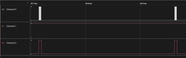
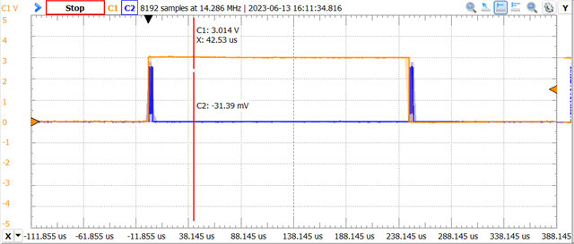
EXPECTED RESULT: CS(orange) toggle high right before SPIM START(blue), and CS toggle low once SPIM END.
ACTUAL RESULT: CS(orange) toggle high right after SPIM START(blue), and CS did not toggle low on SPIM END. Seemed like CS toggle happened only on SPIM END.
CODE2: I did an experiment where I did not toggle CS back on SPIM END.
// NO CS TOGGLE on SPIM END.
nrfx_gppi_channel_endpoints_setup(ppi_channel,
	timer_event_addr,
	cs_task_addr);

nrfx_gppi_fork_endpoint_setup(ppi_channel,
	spim_start_task_addr);

//nrfx_gppi_channel_endpoints_setup(ppi_channel_endSPI,
//	spim_end_event_addr,
//	cs_task_addr);
ACTUAL RESULT 2: CS toggle high before SPIM START, and still CS did not toggle low on SPIM END. Seemed like CS toggle happened only on SPIM START.
I checked with LED and confirmed SPIM END event happened. LED was blinking as expected.
void spim_event_handler(nrfx_spim_evt_t const *p_event, void *p_context)
{
	if (p_event->type == NRFX_SPIM_EVENT_DONE)
	{
		gpio_pin_toggle_dt(&led);
	}
}
Q. Does anybody know the reason for this and how to fix it?
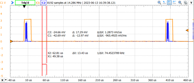
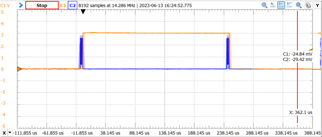
Also, image below shows a happy case where MOSI(blue) gets triggered while CS(orange) gets triggered (4-wire mode ADC).
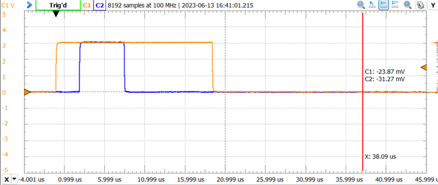
but we found in our case, MOSI stayed low all the time.
According to the documentation, MOSI stays HIGH all the time with 3-wire mode ADC.
Q. How do I know if we are using 3-wire mode or 4-wire mode ADC? How to configure which mode to use?
Q. Any reason why MOSI stays low all the time?
Thank you in advance for your time and effort,
Sincerely,
Skim.