This discussion has been locked.
You can no longer post new replies to this discussion. If you have a question you can start a new discussion

NCS v2.4.0: low power by example

Dear Support team,

I'm involved in the activity to migrate to NCS a project already developed & successfuly tested with using nRF52 SDK v17.1.0, over the custom board initially designed.

That custom board is based on nRF52832_xxAA, battery powered, equipped with an inertial sensor from STM (MEMS) over SPI0, and a 8Mbit flash memory over SPI1, plus some LEDs and one button. The original .dts file is contained in the folder "<ncs_path>\v2.4.0\zephyr\boards\arm\nrf52dk_nrf52832" successfully overlayed for what concerns the custom I/O mapping. Indeed, everything is working fine without MCUBOOT (I'll add it as a final step when everything will be fixed), until I decided to check the power absorbment from the battery that reported around 150 microAmps in "idle" mode (advertising active and the whole system waiting for events).

As I expect an absorbment from 10 to 20 microAmp, I decided to start from the beginning: the "empty" main as reported below:

int main(void)
{
   while(1)
      NRF_POWER->SYSTEMOFF = 1;

   return 0;
}

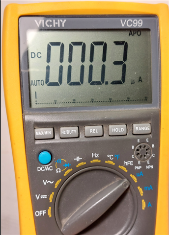
This "empty" main reports 30.0 microAmps (NCS) against the 0.30 microAmps reported by the same "empty" main in the APP built with SDK v17.1.0, anyone could tell me whats's possibly wrong ?


PS: "CONFIG_SERIAL=n" has been applied already as many posts seeemed to be resolutive, also in the overlay "&uart0" is stated as "disabled".

PS #2: already included and built some examples from zephyr/samples/bluetooth (only advertising just to remain basic) and I never saw an absorbment less than 100 microAmps, therefore I can't exclude the extension nRF Connect for VSCode, as it's common to all test made so far

Parents
  • Hi,


    Could you try setting the /CSN pins for these sensors to the inactive? 

    If the SPI Flash is enabled, could you try setting it to a suspended state before entering systemoff?

    dev = DEVICE_DT_GET(DT_NODELABEL(my_device));
    pm_device_action_run(dev, PM_DEVICE_ACTION_SUSPEND);


    Kind regards,

    Håkon

  • Dear Hakon,

    thank you for your prompt reply.

    You got the point, indeed, even if no modules were compiled other than "main.c", there was CONFIG_SPI=y in prj.conf still enabled therefore your doubt about SPI initialized before main() was correct. Now the absorbment is back to 0.3 microAmps as reported from my multimeter (see picture attached).

    Let me take advantage of your availability to ask you a working example of pm_device_action_run() so that I can understand the correct approach to save power when no resource are needed.

    thank you so much for now

    regards, Paolo

  • Hi Hakon,

    Pls confirm if you managed to build without errors, I'm stuck on this point since long time...

    thank you, Paolo

  • Hi Paolo,


    Sorry for the late reply.

    Due to this errata on nRF52832: https://infocenter.nordicsemi.com/topic/errata_nRF52832_Rev3/ERR/nRF52832/Rev3/latest/anomaly_832_58.html#anomaly_832_58

    You must select the configuration: CONFIG_SOC_NRF52832_ALLOW_SPIM_DESPITE_PAN_58=y

    You might also need to set: CONFIG_NRFX_PPI=y


    Please note that this restriction should only be applied if you are certain that you will not trigger the above mentioned anomaly.

    This can also explain why you're not seeing a higher current consumption when selecting "nordic,nrf-spim"; as the above kconfig was blocking you from enabling the SPIx instances.


    Even with all of these set at my end (regardless of nrf,spi or nrf,spim used), I still see < 10 uA sleep with your project.

    You need to check if the additional current goes into your external flash.


    Kind regards,

    Håkon

  • Hello Hakon,

    I switched to nRF52-DK to which I've manually connected the MEMS sensor over SPI and I can confirm very few microAmp when such sensor is powered OFF.

    In order to share something common I still working with sources from "blinky" example (pls find attached).

    Such example turns ON the sensor, then successfuly reads its ID, then turns OFF the sensor in an infinite loop. Unfortunately the sensor doesn't turn OFF because of back-driving from CSN pin, indeed I realized that the call to:

       pm_device_action_run(mems_spi_dev, PM_DEVICE_ACTION_SUSPEND);

    doesn't handle CSN pin because the field that should contain its value reports 255 (NRFX_SPI_PIN_NOT_USED).

    CLK, MISO and MOSI are handled correctly, instead.

    As a proof and just to test, if I modified the zephyr original source code in "nrfx_spi.c" as follows and at last the sensor turned OFF successfully.

    Can you please help me on this ?

    The CSN must be initially configured as the sensor ID is read successfully, so what am I missing ?

    thank you very much in advance, Paolo

    main.c

    /*
     * Copyright (c) 2016 Intel Corporation
     *
     * SPDX-License-Identifier: Apache-2.0
     */
    
    #include <zephyr/kernel.h>
    #include <zephyr/logging/log.h>
    LOG_MODULE_REGISTER(app);
    
    #include <zephyr/drivers/gpio.h>
    #include <zephyr/drivers/spi.h>
    #include <zephyr/pm/device.h>
    #include <nrfx_spi.h>
    
    
    #define OFF 					0
    #define ON						1
    
    #define LIS2DW12_WHO_AM_I	0x0F
    #define LIS2DW12_CTRL2		0x21
    #define LIS2DW12_ID			0x44
    #define MEMS_BOOTUP_MS		(20+20)	// 20ms boot-up (rif.AN5038 pag.34)
    
    
    #define SPI_NODE(idx)					DT_NODELABEL(spi##idx)
    #define SPI_CS_NODE(idx)				DT_NODELABEL(spi##idx##_cs)
    
    
    // MEMS
    static const struct device 			*mems_spi_dev = DEVICE_DT_GET(SPI_NODE(0));
    static const struct spi_cs_control	mems_spi_cs_ctrl = {
    	.gpio = SPI_CS_GPIOS_DT_SPEC_GET(SPI_CS_NODE(0)),
    	.delay = 2
    };
    
    static const struct spi_config 		mems_spi_cfg = {
    	.frequency = 8 * 1000 * 1000,	// 8MHZ
    	.operation = SPI_WORD_SET(8),
    	.cs = &mems_spi_cs_ctrl
    };
    
    #define GPIO0_NODE						DT_NODELABEL(gpio0)
    static const struct device				*gpio0_dev = DEVICE_DT_GET(GPIO0_NODE);
    
    #define MEMS_PWR_NODE					DT_NODELABEL(mems_pwr)
    static const struct gpio_dt_spec 	mems_pwr_spec =
    	GPIO_DT_SPEC_GET(MEMS_PWR_NODE, gpios);
    
    
    #define SPI_BUF_SIZE						256
    static uint8_t								tx_buf[SPI_BUF_SIZE];
    static uint8_t								rx_buf[SPI_BUF_SIZE];
    
    static struct spi_buf 					tx_spi_bufs[] = {
    	{
    		.buf = tx_buf
    	}
    };
    
    static struct spi_buf 					rx_spi_bufs[] = {
    	{
    		.buf = rx_buf
    	}
    };
    
    static const struct spi_buf_set 		spi_tx_buf_set = {
    	.buffers = tx_spi_bufs,
    	.count = 1
    };
    
    static const struct spi_buf_set 		spi_rx_buf_set = {
    	.buffers = rx_spi_bufs,
    	.count = 1
    };
    
    #define TX_RX_MSG_LENGTH				256
    static uint8_t								m_tx_data_spi[TX_RX_MSG_LENGTH]; ///< SPI TX buffer.
    
    
    uint8_t mems_power(uint8_t p)
    {
    	if (p)
    	{
    		gpio_pin_configure_dt(&mems_pwr_spec, GPIO_OUTPUT);
    		gpio_pin_set_dt(&mems_pwr_spec, ON);
    	}
    	else
    	{
    		// gpio_pin_configure_dt(&mems_pwr_spec, GPIO_INPUT);
    		gpio_pin_configure_dt(&mems_pwr_spec, GPIO_OUTPUT);
    		gpio_pin_set_dt(&mems_pwr_spec, OFF);
    	}
    
    	k_msleep(MEMS_BOOTUP_MS);
    
    	return 0;	// OK
    }
    
    uint8_t mems_spi_read(uint8_t addr, void *val, uint8_t len)
    {
    	__ASSERT_NO_MSG(len < SPI_BUF_SIZE);
    
    	tx_buf[0] = addr | BIT(7);
    
    	tx_spi_bufs[0].len =
    	rx_spi_bufs[0].len = 1+len;
    
    	int err = spi_transceive(mems_spi_dev, &mems_spi_cfg,
    									 &spi_tx_buf_set, &spi_rx_buf_set);
    	if (err < 0)
    	{
    		LOG_WRN("transceive() failed! err=%d", err);
    		return 1;	// KO
    	}
    
    	//LOG_HEXDUMP_DBG(rx_buf, 1+len, "rx");
    	memcpy(val, rx_buf+1, len);
    
    	return 0;	// OK
    }
    
    void mems_check_id(void)
    {
    	char buf[4];
    
    	mems_spi_read(LIS2DW12_WHO_AM_I, buf, 1);
    	LOG_INF("mems_check: id=x%X/x%X", *buf, LIS2DW12_ID);
    }
    
    int spi_init(void)
    {
    	if (!device_is_ready(mems_spi_dev))
    		return 1;
    
    	return 0;
    }
    
    int main(void)
    {
    	while (1)
    	{
    		mems_power(ON);
    		k_msleep(1000);
    
    		mems_check_id();
    		k_msleep(1000);
    
    		mems_power(OFF);
    		k_msleep(1000);
    
    		pm_device_action_run(mems_spi_dev, PM_DEVICE_ACTION_SUSPEND);
    		k_msleep(1000);
    	}
    
    	return 0;
    }
    

    board.overlay

    // To get started, press Ctrl+Space to bring up the completion menu and view the available nodes.
    
    // You can also use the buttons in the sidebar to perform actions on nodes.
    // Actions currently available include:
    
    // * Enabling / disabling the node
    // * Adding the bus to a bus
    // * Removing the node
    // * Connecting ADC channels
    
    // For more help, browse the DeviceTree documentation at https://docs.zephyrproject.org/latest/guides/dts/index.html
    // You can also visit the nRF DeviceTree extension documentation at https://nrfconnect.github.io/vscode-nrf-connect/devicetree/nrfdevicetree.html
    
    &sram0 {
    	reg = <0x20000000 (DT_SIZE_K(64)-128)>;
    };
    
    &pinctrl {
    	spi0_default: spi0_default {
    		group1 {
    			psels = <NRF_PSEL(SPIM_SCK, 0, 14)>,
    				<NRF_PSEL(SPIM_MOSI, 0, 16)>,
    				<NRF_PSEL(SPIM_MISO, 0, 15)>;
    		};
    	};
    
    	spi0_sleep: spi0_sleep {
    		group1 {
    			psels = <NRF_PSEL(SPIM_SCK, 0, 14)>,
    				<NRF_PSEL(SPIM_MOSI, 0, 16)>,
    				<NRF_PSEL(SPIM_MISO, 0, 15)>;
    			low-power-enable;
    		};
    	};
    
    	spi1_default: spi1_default {
    		group1 {
    			psels = <NRF_PSEL(SPIM_SCK, 0, 7)>,
    				<NRF_PSEL(SPIM_MOSI, 0, 6)>,
    				<NRF_PSEL(SPIM_MISO, 0, 3)>;
    		};
    	};
    
    	spi1_sleep: spi1_sleep {
    		group1 {
    			psels = <NRF_PSEL(SPIM_SCK, 0, 7)>,
    				<NRF_PSEL(SPIM_MOSI, 0, 6)>,
    				<NRF_PSEL(SPIM_MISO, 0, 3)>;
    			low-power-enable;
    		};
    	};
    };
    
    &i2c0 {
    	status = "disabled";
    };
    
    &spi0 {
    	//compatible = "nordic,nrf-spi";
    	status = "okay";
    	// cs-gpios = <&gpio0 18 GPIO_ACTIVE_LOW>;
    	cs-gpios = <&gpio0 13 GPIO_ACTIVE_LOW>;
    	spi0_cs: spi0_cs@0 {
    		reg = <0>;
    	};
    };
    
    &spi1 {
    	//compatible = "nordic,nrf-spi";
    	cs-gpios = <&gpio0 2 GPIO_ACTIVE_LOW>;
    	spi1_cs: spi1_cs@0 {
    		reg = <0>;
    	};
    };
    
    &spi2 {
    	status = "disabled";
    };
    
    &uart0 {
    	status = "disabled";
    };
    
    &arduino_serial {
    	status = "disabled";
    };
    
    &arduino_spi {
    	status = "disabled";
    };
    
    &arduino_i2c {
    	status = "disabled";
    };
    
    &pwm0 {
    	status = "disabled";
    };
    
    &led0 {
    	status = "disabled";
    };
    
    &led1 {
    	status = "disabled";
    };
    
    &led2 {
    	status = "disabled";
    };
    
    &led3 {
    	status = "disabled";
    };
    
    &pwm_led0 {
    	status = "disabled";
    };
    
    &button0 {
    	status = "disabled";
    };
    
    &button1 {
    	status = "disabled";
    };
    
    &button2 {
    	status = "disabled";
    };
    
    &button3 {
    	status = "disabled";
    };
    
    / {
    	ingressi {
    		compatible = "gpio-keys";
    		button: button {
    			gpios = <&gpio0 11 GPIO_ACTIVE_HIGH>;
    		};
    		mems_int: mems_int {
    			gpios = <&gpio0 14 GPIO_ACTIVE_HIGH>;
    		};
    	};
    };
    
    / {
    	uscite {
    		compatible = "gpio-leds";
    		led_red: led_red {
    			gpios = <&gpio0 24 GPIO_ACTIVE_LOW>;
    		};
    		led_green: led_green {
    			gpios = <&gpio0 22 GPIO_ACTIVE_LOW>;
    		};
    		led_blue: led_blue {
    			gpios = <&gpio0 23 GPIO_ACTIVE_LOW>;
    		};
      		mems_pwr: mems_pwr {
      			gpios = <&gpio0 12 GPIO_ACTIVE_HIGH>;
    		};
    		extm_pwr: extm_pwr {
    			gpios = <&gpio0 8 GPIO_ACTIVE_LOW>;
    		};
    		extm_rst: extm_rst {
    			gpios = <&gpio0 5 GPIO_ACTIVE_LOW>;
    		};
    		extm_wp: extm_wp {
    			gpios = <&gpio0 4 GPIO_ACTIVE_LOW>;
    		};
    		adc_vbatt: adc_vbatt {
    			gpios = <&gpio0 30 GPIO_ACTIVE_LOW>;
    		};
    	};
    };
    
    // MCU boot single slot configuration
    // /delete-node/ &boot_partition;
    // /delete-node/ &slot0_partition;
    // /delete-node/ &slot1_partition;
    
    // &flash0 {
    // 	partitions {
    // 			compatible = "fixed-partitions";
    // 			#address-cells = <1>;
    // 			#size-cells = <1>;
    
    // 			boot_partition: partition@0 {
    // 				label = "mcuboot";
    // 				reg = <0x000000000 0x0000c000>;
    // 			};
    // 			slot0_partition: partition@c000 {
    // 				label = "image-0";
    // 				reg = <0x00000c000 0x00006e000>;
    // 			};
    // 	};
    // };
    

    board.dts

    /*
     * Copyright (c) 2017 Shawn Nock <[email protected]>
     * Copyright (c) 2017 Linaro Limited
     *
     * SPDX-License-Identifier: Apache-2.0
     */
    
    /dts-v1/;
    #include <nordic/nrf52832_qfaa.dtsi>
    #include "nrf52dk_nrf52832-pinctrl.dtsi"
    
    / {
    	model = "Nordic nRF52 DK NRF52832";
    	compatible = "nordic,nrf52-dk-nrf52832";
    
    	chosen {
    		zephyr,console = &uart0;
    		zephyr,shell-uart = &uart0;
    		zephyr,uart-mcumgr = &uart0;
    		zephyr,bt-mon-uart = &uart0;
    		zephyr,bt-c2h-uart = &uart0;
    		zephyr,sram = &sram0;
    		zephyr,flash = &flash0;
    		zephyr,code-partition = &slot0_partition;
    	};
    
    	leds {
    		compatible = "gpio-leds";
    		led0: led_0 {
    			gpios = <&gpio0 17 GPIO_ACTIVE_LOW>;
    			label = "Green LED 0";
    		};
    		led1: led_1 {
    			gpios = <&gpio0 18 GPIO_ACTIVE_LOW>;
    			label = "Green LED 1";
    		};
    		led2: led_2 {
    			gpios = <&gpio0 19 GPIO_ACTIVE_LOW>;
    			label = "Green LED 2";
    		};
    		led3: led_3 {
    			gpios = <&gpio0 20 GPIO_ACTIVE_LOW>;
    			label = "Green LED 3";
    		};
    	};
    
    	pwmleds {
    		compatible = "pwm-leds";
    		pwm_led0: pwm_led_0 {
    			pwms = <&pwm0 0 PWM_MSEC(20) PWM_POLARITY_INVERTED>;
    		};
    	};
    
    	buttons {
    		compatible = "gpio-keys";
    		button0: button_0 {
    			gpios = <&gpio0 13 (GPIO_PULL_UP | GPIO_ACTIVE_LOW)>;
    			label = "Push button switch 0";
    		};
    		button1: button_1 {
    			gpios = <&gpio0 14 (GPIO_PULL_UP | GPIO_ACTIVE_LOW)>;
    			label = "Push button switch 1";
    		};
    		button2: button_2 {
    			gpios = <&gpio0 15 (GPIO_PULL_UP | GPIO_ACTIVE_LOW)>;
    			label = "Push button switch 2";
    		};
    		button3: button_3 {
    			gpios = <&gpio0 16 (GPIO_PULL_UP | GPIO_ACTIVE_LOW)>;
    			label = "Push button switch 3";
    		};
    	};
    
    	arduino_header: connector {
    		compatible = "arduino-header-r3";
    		#gpio-cells = <2>;
    		gpio-map-mask = <0xffffffff 0xffffffc0>;
    		gpio-map-pass-thru = <0 0x3f>;
    		gpio-map = <0 0 &gpio0 3 0>,	/* A0 */
    			   <1 0 &gpio0 4 0>,	/* A1 */
    			   <2 0 &gpio0 28 0>,	/* A2 */
    			   <3 0 &gpio0 29 0>,	/* A3 */
    			   <4 0 &gpio0 30 0>,	/* A4 */
    			   <5 0 &gpio0 31 0>,	/* A5 */
    			   <6 0 &gpio0 11 0>,	/* D0 */
    			   <7 0 &gpio0 12 0>,	/* D1 */
    			   <8 0 &gpio0 13 0>,	/* D2 */
    			   <9 0 &gpio0 14 0>,	/* D3 */
    			   <10 0 &gpio0 15 0>,	/* D4 */
    			   <11 0 &gpio0 16 0>,	/* D5 */
    			   <12 0 &gpio0 17 0>,	/* D6 */
    			   <13 0 &gpio0 18 0>,	/* D7 */
    			   <14 0 &gpio0 19 0>,	/* D8 */
    			   <15 0 &gpio0 20 0>,	/* D9 */
    			   <16 0 &gpio0 22 0>,	/* D10 */
    			   <17 0 &gpio0 23 0>,	/* D11 */
    			   <18 0 &gpio0 24 0>,	/* D12 */
    			   <19 0 &gpio0 25 0>,	/* D13 */
    			   <20 0 &gpio0 26 0>,	/* D14 */
    			   <21 0 &gpio0 27 0>;	/* D15 */
    	};
    
    	arduino_adc: analog-connector {
    		compatible = "arduino,uno-adc";
    		#io-channel-cells = <1>;
    		io-channel-map = <0 &adc 1>,	/* A0 = P0.3 = AIN1 */
    				 <1 &adc 2>,	/* A1 = P0.4 = AIN2 */
    				 <2 &adc 4>,	/* A2 = P0.28 = AIN4 */
    				 <3 &adc 5>,	/* A3 = P0.29 = AIN5 */
    				 <4 &adc 6>,	/* A4 = P0.30 = AIN6 */
    				 <5 &adc 7>;	/* A5 = P0.31 = AIN7 */
    	};
    
    	/* These aliases are provided for compatibility with samples */
    	aliases {
    		led0 = &led0;
    		led1 = &led1;
    		led2 = &led2;
    		led3 = &led3;
    		pwm-led0 = &pwm_led0;
    		sw0 = &button0;
    		sw1 = &button1;
    		sw2 = &button2;
    		sw3 = &button3;
    		bootloader-led0 = &led0;
    		mcuboot-button0 = &button0;
    		mcuboot-led0 = &led0;
    		watchdog0 = &wdt0;
    	};
    };
    
    &adc {
    	status = "okay";
    };
    
    &gpiote {
    	status = "okay";
    };
    
    &gpio0 {
    	status = "okay";
    };
    
    arduino_serial: &uart0 {
    	status = "okay";
    	compatible = "nordic,nrf-uarte";
    	current-speed = <115200>;
    	pinctrl-0 = <&uart0_default>;
    	pinctrl-1 = <&uart0_sleep>;
    	pinctrl-names = "default", "sleep";
    };
    
    arduino_i2c: &i2c0 {
    	compatible = "nordic,nrf-twi";
    	status = "okay";
    	pinctrl-0 = <&i2c0_default>;
    	pinctrl-1 = <&i2c0_sleep>;
    	pinctrl-names = "default", "sleep";
    };
    
    &i2c1 {
    	compatible = "nordic,nrf-twi";
    	/* Cannot be used together with spi1. */
    	/* status = "okay"; */
    	pinctrl-0 = <&i2c1_default>;
    	pinctrl-1 = <&i2c1_sleep>;
    	pinctrl-names = "default", "sleep";
    };
    
    &pwm0 {
    	status = "okay";
    	pinctrl-0 = <&pwm0_default>;
    	pinctrl-1 = <&pwm0_sleep>;
    	pinctrl-names = "default", "sleep";
    };
    
    &spi0 {
    	compatible = "nordic,nrf-spi";
    	/* Cannot be used together with i2c0. */
    	/* status = "okay"; */
    	pinctrl-0 = <&spi0_default>;
    	pinctrl-1 = <&spi0_sleep>;
    	pinctrl-names = "default", "sleep";
    };
    
    &spi1 {
    	compatible = "nordic,nrf-spi";
    	status = "okay";
    	pinctrl-0 = <&spi1_default>;
    	pinctrl-1 = <&spi1_sleep>;
    	pinctrl-names = "default", "sleep";
    };
    
    arduino_spi: &spi2 {
    	compatible = "nordic,nrf-spi";
    	status = "okay";
    	cs-gpios = <&arduino_header 16 GPIO_ACTIVE_LOW>; /* D10 */
    	pinctrl-0 = <&spi2_default>;
    	pinctrl-1 = <&spi2_sleep>;
    	pinctrl-names = "default", "sleep";
    };
    
    &flash0 {
    
    	partitions {
    		compatible = "fixed-partitions";
    		#address-cells = <1>;
    		#size-cells = <1>;
    
    		boot_partition: partition@0 {
    			label = "mcuboot";
    			reg = <0x00000000 0xc000>;
    		};
    		slot0_partition: partition@c000 {
    			label = "image-0";
    			reg = <0x0000C000 0x37000>;
    		};
    		slot1_partition: partition@43000 {
    			label = "image-1";
    			reg = <0x00043000 0x37000>;
    		};
    		storage_partition: partition@7a000 {
    			label = "storage";
    			reg = <0x0007a000 0x00006000>;
    		};
    	};
    };
    

    prj.conf

    CONFIG_GPIO=y
    CONFIG_SPI=y
    CONFIG_ASSERT=y
    CONFIG_LOG=y
    CONFIG_PM=y
    CONFIG_PM_DEVICE=y
    

  • Forgot to notice another modify I've done in "spi_nrfx_spi.c" as follows:

  • Hi,


    You are changing things you should not change now.

    The SPI module handles the /CS pin on demand. Scope the SPI pins instead (or check the NRF_SPI0 register content after running).

    pzuck said:

    doesn't handle CSN pin because the field that should contain its value reports 255 (NRFX_SPI_PIN_NOT_USED).

    /CSN pin only goes active when you try to send data. Please note that it is setup as active low, ie. inactive high.


    pzuck said:
    then turns OFF the sensor in an infinite loop.

    Do you also cut power to the sensor? If yes, then you need to set all GPIOs that is connected to it to a low level.


    Kind regards,

    Håkon

Reply
  • Hi,


    You are changing things you should not change now.

    The SPI module handles the /CS pin on demand. Scope the SPI pins instead (or check the NRF_SPI0 register content after running).

    pzuck said:

    doesn't handle CSN pin because the field that should contain its value reports 255 (NRFX_SPI_PIN_NOT_USED).

    /CSN pin only goes active when you try to send data. Please note that it is setup as active low, ie. inactive high.


    pzuck said:
    then turns OFF the sensor in an infinite loop.

    Do you also cut power to the sensor? If yes, then you need to set all GPIOs that is connected to it to a low level.


    Kind regards,

    Håkon

Children
  • Hi,

    I wouldn't change Zephyr code but is quite clear that without those changes the pm_device_action_run(SUSPEND) doesn't handle /CSN as spi_transceive() instead does.

    Indeed, when I cut the power to the sensor, it remains powered from /CSN, until I set /CSN to low.

    Please have a look at the Zephyr sources, in particolar "spi_nrfx_spi.c" where the field "skip_gpio_cfg" is initialized to TRUE: this initialization prevent any PIN re-configuration from pm_device_action_run(SUSPEND).

    Do you have an idea of why that hard-coded initialization ?

    Furthermore, why the field .ss_csn is not loaded with the correct pin value ?

    Everything seems to be strange, I'm worried about the possibility to have made a mistake somewhere in the configuration files.


    thank you, Paolo

  • pzuck said:
    Please have a look at the Zephyr sources, in particolar "spi_nrfx_spi.c" where the field "skip_gpio_cfg" is initialized to TRUE: this initialization prevent any PIN re-configuration from pm_device_action_run(SUSPEND).

    It is setup this way on purpose, and allows the module/driver that uses it to configure it on-the-fly.

    I would strongly recommend that you use a logic analyzer or a oscilloscope to verify the pin states.

    pzuck said:
    Furthermore, why the field .ss_csn is not loaded with the correct pin value ?

    It highly likely is, just at a later point in time.


    Kind regards,

    Håkon

  • Hi Hakon,

    What's happen is clear to me as I followed the code step by step with the debugger and checked the pin states with an oscilloscope.

    I can confirm also that the sensor communications over SPI are OK, just I wanted to turn it OFF by using pm_device_action_run(...SUSPEND).

    Can't understand why you don't want to get the evidences reported and answer properly.

    thank you, Paolo

  • Hi Paulo,


    Regarding the .ss_pin member: there is a difference on how the module(s) work at boot-time vs. how they work when actually used.

    On boot-up, it will skip the gpio configuration, while when addressed and used in main.c, the configuration will be passed to the spi_nrfx_spi.c and be configured on each run.

    As the SPI hardware peripheral does not have a dedicated /CSN pin, this is handled by the gpio driver.


    Here's the minimal main.c (based on your code):

    /*
     * Copyright (c) 2012-2014 Wind River Systems, Inc.
     *
     * SPDX-License-Identifier: Apache-2.0
     */
    
    #include <zephyr/kernel.h>
    #include <zephyr/logging/log.h>
    #include <zephyr/drivers/gpio.h>
    #include <zephyr/drivers/spi.h>
    #include <zephyr/pm/device.h>
    
    LOG_MODULE_REGISTER(app);
    
    #define SPI_BUF_SIZE 16
    #define MY_SPI_NODE spi0
    
    static const struct device *spi_dev = DEVICE_DT_GET(DT_NODELABEL(MY_SPI_NODE));
    static const struct spi_cs_control spi_cs_ctrl = {
    	.gpio = GPIO_DT_SPEC_GET(DT_NODELABEL(MY_SPI_NODE), cs_gpios),
    	.delay = 2
    };
    
    static const struct spi_config spi_cfg = {
    	.frequency = 8 * 1000 * 1000,
    	.operation = SPI_WORD_SET(8),
    	.cs = &spi_cs_ctrl
    };
    
    static uint8_t tx_buf[SPI_BUF_SIZE];
    static uint8_t rx_buf[SPI_BUF_SIZE];
    
    static struct spi_buf tx_spi_bufs[] = {
    	{
    		.len = 4,
    		.buf = tx_buf
    	}
    };
    
    static struct spi_buf rx_spi_bufs[] = {
    	{
    		.len = 4,
    		.buf = rx_buf
    	}
    };
    
    static const struct spi_buf_set	spi_tx_buf_set = {
    	.buffers = tx_spi_bufs,
    	.count = 1
    };
    
    static const struct spi_buf_set	spi_rx_buf_set = {
    	.buffers = rx_spi_bufs,
    	.count = 1
    };
    
    uint8_t test_spi_read(uint8_t addr, uint8_t len)
    {
    	__ASSERT_NO_MSG(len < SPI_BUF_SIZE);
    
    	tx_buf[0] = addr | BIT(7);
    
    	tx_spi_bufs[0].len = rx_spi_bufs[0].len = len;
    
    	int err = spi_transceive(spi_dev, &spi_cfg, &spi_tx_buf_set, &spi_rx_buf_set);
    	if (err < 0)
    	{
    		LOG_WRN("transceive() failed! err=%d", err);
    		return 1;
    	} else {
    		LOG_INF("OK");
    	}
    	return 0;
    }
    
    int main(void)
    {
    	printk("Hello World! %s\n", CONFIG_BOARD);
    	while (1) {
    		test_spi_read(0, 2);
    		/* Keep it active for testing purposes */
    		k_msleep(1000);
    		pm_device_action_run(spi_dev, PM_DEVICE_ACTION_SUSPEND);
    		k_msleep(1000);
    		pm_device_action_run(spi_dev, PM_DEVICE_ACTION_RESUME);
    		k_msleep(1);
    	}
    }

    Here's a scope of the SPI communication on &spi0 (P0.26/P0.27/P0.28, CSN=P0.13):

    And here's the overlay that I used:

    &spi0 {
            //compatible = "nordic,nrf-spi";
            status = "okay";
            // cs-gpios = <&gpio0 18 GPIO_ACTIVE_LOW>;
            cs-gpios = <&gpio0 13 GPIO_ACTIVE_LOW>;
            spi0_cs: spi0_cs@0 {
                    reg = <0>;
            };
    };

    As I do not have any sensor connected on the SPI bus, there's no response on MISO.


    And here's the power consumption:

    pzuck said:
    Indeed, when I cut the power to the sensor, it remains powered from /CSN, until I set /CSN to low.

    This is as intended. If you are powering off your external sensor, you need to ensure that all GPIOs/signals going to your external sensor are kept at GND level.


    Kind regards,

    Håkon

  • Hi Hakon,

    In your scope screenshot I don't see /CSN going low for 1 sec by the call:

           pm_device_action_run(spi_dev, PM_DEVICE_ACTION_SUSPEND);

    therefore the sensor (virtual in your scenario) will never turn OFF.

    If everything worked we should see two times CS hi-low-hi transaction. The first very short as SPI read from sensor, the second with a duration of 1000 ms

    Let me know

    thank you, Paolo

Related