Replacing RS485 link with NRF24L01+

As Pevious ticket: Using NRF24L01+ with pure assembler programing becomes very long,  I open a new one as Torbjørn suggested

This is a description about what I have doing in my proyect and at the end there are some questions.

.......................................................................................

My application has a Central unit connected to several Handheld controllers  with RS485 cable.
Bit rate is 62.500 , 9bits

The central unit is sending in secuence a Callbyte for each Handheld address (from1 to 31) and wait about 100 us for a reply, before it will send a Callbyte to the following address
In this cable system a Handheld only changes to Tx mode after a Callbyte with his address is received.

The Central unit has connected two rails for Model Electric trains. (Ferromedelism)

I will add an interfase  with a uP and a NRF24L04p that will handle the RF link and connected to the Central by 485 cable
No modifications at the Central unit hadware or software willbemade.

The the handheld will be re-designated by adding one NRF24L01+, removing the 485 part and modifying the program as needed.

Using the usual star configuration , the intefase will use PRX mode and may be up to 6 handheldwill using the NRF part in PTX mode.

All the 485 packets are 9 bits but the MSB is only for the information about if the byte is an Address (= 1) or a DATA  (= 0)

Only the Central may send Address and Data bytes.   Handheld units only send DATA bytes

In my aproach the interfase unit decodes only the Callbytes and the NRF will need to handle only 8 bits.

There are 3 types of Callbytes:

1) Callbytes with no more bytes in the packet, that allows the matching address Handheld to

send a packet to the central

2) Callbytes with 1 or more DATA with information requested before by one specific handheld.

The regarding address will be in the Callbyte

3) Broadcast Callbytes: The packet will have information that must be sent to all the Handhelds units.

The program for the interfase unit has 6 RX buffers and 6 TX buffers for the USART and 485 , one pair for each PIPE

Data send from a Handheld by NRF is received by interfase and stored in the TX buffer , for case 1)

Data received by USART (from RS485) is stored in Rx buffer and loaded in NRF TXFIFO  for sending it as an ACK PAYLOAD

I will use some time slots system (not defined yet) for each PTX for avoid collitions and to get back  information when available

------------------------- Some quetions here ---------------------

At the moment the matter  1) is working OK   

Each information sent from Handheld is received at interfase side and sent by RS485 when type 1) Callbyte arrives.

For cases 2) and 3)  ,  information from Handheld is received but ACK PAYLOAD is sent some times yes  other times no

uP reset do not helps .  If the NRF supply is disconected and reconected, ACK PAYLOAD begins to work

It may be  working in all the PTX packets or alternately one yes one not.

I have a low cost , 8 channels Logic Analizer and I will investigate this problem by reading STATUS and FIFO_STATUS

I guess the problem is at PRX side, not sending ACK, but I am no sure.

Please send any suggestion about where it may be the problem.

Also how to diferenciate  which side is not working well.

Best Regards, Osvaldo Hojvat

Parents
  • Hi Osvaldo

    Do you upload multiple ACK payloads in the nRF24L01+ FIFO's at once, or only one at a time? 

    What if you flush the TX FIFO on the PRX side, is this not enough to get ACK payloads to work again?

    Since the buffer is a simple FIFO it doesn't handle the situation very well where you have multiple packets intended for different pipes. The following snippet from the datasheet describes this issue:

    If the TX FIFO (PRX) contains more than one payload to a PTX, payloads are handled using the first in – first out principle. The TX FIFO (PRX) is blocked if all pending payloads are addressed to a PTX where the link is lost. In this case, the MCU can flush the TX FIFO (PRX) by using the FLUSH_TX command.

    Best regards
    Torbjørn

  • Thank you for your reply

    I upload information for one pipe in case 2) or 3 pipes in case 3)

    I had readed this data sheet information and used flush Tx FIFO and Rx FIFO at PTX side but not yet at PRX side

    I will add and test again.

    I guess that flush will erase the 3 levels of FIFO

    I need to use the POWER ON delay of uP in the PRX because some unwanted signals arises in SPI at power-up

    Recently I change Logic Analyzer cables with 4 to PRX SPI and 4 to PTX SPI and have a capture after / later re-seting PRX

    I will check this information and I will make a summary

    As I add some FIFO sate reading, it may be usefull information about the problem.

    Regards, Osvaldo

  • I found the cause by looking at bit 0 of STATUS in the first SPI messages on the PRX
    I have a wired handheld connected to the control panel, and its address is 12
     It is in the range of 10 to 15 that can be used for RF, for some tests what did I do.
     At the start, this unit requests and receives information from the control panel and because it is in range, the interface receives it by cable and upload it to send it by NRF.
    The PTX that is working has address 10 (PIPE = 0) and it do not attend packets to 12 ( PIPE 2) They accumulate in the buffer and stop everything.
    Disconected handheld 12 (or change it address to 9) and RF link works fine from power-up

    Test again with address 10 in the handheld and the packets are sended with ack when PTX sends a new packet and also there are pending packets received at PTX 

    At the moment the PTX-PRX is working well as follows:
    With a pushbuttom at PTX  there is one message sent to the Central requesting some information.
    The reply is ulpoad with the ACK but it is not sent until the next packet sent from PTX.
    This is OK as expected.  In the proyect the PTX must send periodically packets


     Please tell me when to use waiting times and where they are necessary.


     Regards Osvaldo

  • Hi Osvaldo

    o.hojvat said:
    I guess that flush will erase the 3 levels of FIFO

    Yes. A flush will clear all the packets currently in the FIFO. In order to avoid packet loss you might need to buffer the packets in the host MCU as well, so that you can upload them to the nRF device after the flush. 

    o.hojvat said:
    The reply is ulpoad with the ACK but it is not sent until the next packet sent from PTX.
    This is OK as expected.  In the proyect the PTX must send periodically packets

    It sounds like you were able to figure out the issues then? In the end it was a problem of having the wrong address?

    o.hojvat said:
    Please tell me when to use waiting times and where they are necessary.

    If you check chapter 6.1.7 on page 24 in the nRF24L01+ Product Specification it explains the most important timing parameters, such as the time it takes to power up the chip from power down, and the time it takes to start the radio. 

    The protocol timing requirements is covered by chapter 7.7 on page 42. 

    Best regards
    Torbjørn

  • I have  measured some delay times and found that sending a packet from PTX and get the reply available again at PRX takes about 2,5ms in total

    This includes NRF tx -rx times to interfase and USART times and reply from central unit by 485 cable

    In my future time division schema , I guess 20ms for each PTX, so it will be 120ms from each PTX trasmition to the following for the ack payload of previus packet.

    In the 20ms slot PTX can send a packet and after after 2,5 ms the reply will upload as ACK payload at PRX

    My last idea is at by example  5ms from the  first packet sent, the PTX will send a second special packet one byte length, only to geting the ACK PAYLOAD information.

    This byte will have a special code ("F0" by example) that tells PRX it is not to be send by the USART (as it is done for all the usual packets)

    In this way the reply will be at PRX in the same 20ms time slot

    This one byte packet will be send all the lime to keep syncronized the PTx

    Aditionally the most important advantage is to avoid TXFIFO full in PRX

    The case 3) broadcast packet, it will be loaded in the 6 microprocesor buffers (in PRX =  interfase) an loaded to the PRX  TxFIFO  one in each slot time , a little before the expected one byte repetitive packet.

    So I will begin using all 6 address PIPES and time slot matter, before include the short test program in the complete handheld one.

    Until now I never change the default address in NRF

    The 6 USART address matter was make an well tested .  Handheld with 485 cable with several different address  was used  for this purpose,

    ..............................................................

    The problem with wrong address arises because I used a normal handheld with cable to generate and receive USART signals in the debug.

    I was not the problem because an error remaining in the interfase (with the PRX) program but it was an error or confusion in the tests..

    ....................................

    With the repetitive special packet it may be more simple to identificate PIPES not in use or out of range PTX

    Best Regards, Osvaldo

  • There is a time of about 130us for PRX changes from Rx to Tx

    Meanwhile:

    For SPI it is posible to do an upload for the ack payload (6 byte packet) in about  20 us, inmediately IRQ of PRX goes low.

    But may it works ?

    Regards, Osvaldo

Reply Children
  • Hi Osvaldo

    You should be able to buffer regular payloads (PTX) or ACK payloads (PRX) independently of what the radio is currently doing. As an example, it is fine to upload multiple payloads while the radio is busy ramping up. 

    o.hojvat said:
    For SPI it is posible to do an upload for the ack payload (6 byte packet) in about  20 us, inmediately IRQ of PRX goes low.

    You mean the IRQ goes low immediately after uploading an ACK payload? 
    This sounds odd. 

    On the PRX side you should not expect an interrupt unless you receive a packet from the PTX, uploading an ACK payload on the PRX side will have no influence on when the PTX sends you data. 

    Best regards
    Torbjørn

  • I will try to explain myself better:

         I know that the ack payload must be loaded before receiving the packet in the PRX, so that it goes transmitted together with the next ACK.

         In the data sheet I can't find information about time margins regarding the IRQ go to low level and the upload timming

        What happens if the upload is done in the first 20 us after the IRQ goes low at PRX side ?

         The RF part takes 300 us to go to TX (PLL lock) and may be at the beginning of this time the payload can be loaded in the TX FIFO, to be transmitted next .

      I can do some tests, but perhaps this matter has already been analyzed

    Best Regards, Osvaldo Hojvat

  • Hi Torbjørn

    I have many parts of my project working as expected.

    There is a disappointing problem:  the system works but it depends on the order of PRX or PTX started first.

    The system may be locked because tx FIFO or Rx FIFO full or Max retry number.

     Since I have a Tx from PTx each 128ms , I can do some FLUSH for FIFOS and clear STATUS flags on PRX and/or PTX sides if there are no packets for example in 200ms.

     I am asking if there are some recommendations that are usual for this matter.

    ------------------------------------------------------

    By the way I have one idea to share

            About  SPI speed,  working with PIC18F26Q10  I have used 16 MHZ sending data to a flash memory and 5MHz when receiving data.    This meets time specifications for both parts and works fine.

    It is usefull in my aplication because I send 4bytes for command and address and get 4 data bytes in each access for reading. 

    For NRF I used 4MHz by the moment..

    Best Regards


  • Hi Osvaldo

    o.hojvat said:
        What happens if the upload is done in the first 20 us after the IRQ goes low at PRX side ?

    In order for the packet upload to be included in the ACK the entire packet upload procedure has to complete before the IRQ goes low as a result of an incoming packet. If the packet upload completes after the IRQ has gone low it is already too late, and the packet will only be returned on the next packet from the PTX. 

    o.hojvat said:
    The RF part takes 300 us to go to TX (PLL lock) and may be at the beginning of this time the payload can be loaded in the TX FIFO, to be transmitted next .

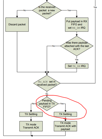
    Unfortunately you can not upload a packet while the TX is settling and have it included immediately. If you check the state diagram in chapter 7.5.2 you will see that the FIFO status is checked before enabling the radio in TX mode. If there are no packets in the TX FIFO the radio will go back to RX mode immediately:

    Also, please note that TX settling time is 130us, not 300us. 

    o.hojvat said:
    There is a disappointing problem:  the system works but it depends on the order of PRX or PTX started first.

    The system may be locked because tx FIFO or Rx FIFO full or Max retry number.

    If you get into problems when starting the PRX first you could put some code on the PRX side to avoid uploading any ACK payloads until at least one packet is received from the PTX. Then you know that you won't fill the TX FIFO on the PRX side until the PTX is ready to pick them up. 

    o.hojvat said:
    The system may be locked because tx FIFO or Rx FIFO full or Max retry number.

     Since I have a Tx from PTx each 128ms , I can do some FLUSH for FIFOS and clear STATUS flags on PRX and/or PTX sides if there are no packets for example in 200ms.

    Yes, you can use a timeout on the PRX side to detect situations where the PTX is not sending any data for a long time, and flush the FIFO's accordingly. 

    If nothing is received for a certain amount of time you might want to just flush the FIFO and immediately upload a new, updated ACK payload. As long as nothing is received simply repeat this procedure. If nothing is received for a very long time you might consider using a longer timeout value, until the PTX starts responding again. 

    Best regards
    Torbjørn


  • Hi Torbjørn

    Thank you very much for your always kind answer. I will take into account all your suggestions.

    Now I'm trying to get the synchronization of the PTX timer with the PRX timer working, using the periodic transmission which is necessary anyway.

     Every 128ms PTX sends a packet that starts with F5 and then the value of its PTXtimer, which will always be the same at this moment.

     PRX recognizes F5 code and only loads the value of the difference (PRXtimer - PTXtimer) as ACK payload
    .
     PTX receives it and adds that value to the PTX timer with which it remains synchronized.

    The total time is 420us and the timers advance every 500us, so there is no problem that they change during the process.

    I used transmit the difference in case there is a delay due to ret-ransmissions o other, but I can measure and correct that.
     
    This way it seems to work OK, but a few times it initiates and remains oscillating indefinitely.

    It is not easy to start the fault.     It is fixed when the PTX sends a normal use packet inserted and the next one with F5 does not update.

     As it is a feedback system and with delays, I tried to correct using half the difference and the oscillation is damped in 1 to 2 seconds.
     
    This is acceptable but I want to understand how it works and correct it properly.

     Now I believe that it should not be corrected in all packets.

     I have to analyze well the capture of the 8 channels of the logic analyzer, 4 of the SPI of the PTX and 4 of the PRX.

     I will send the result when I have it solved.

    Best Regards, Osvaldo

Related