SPIM3 peripheral not reliable

Environment: NCS v2.0.2

Chip: NRF52840_xxAA_REV2

Board: Custom pre-production board

Hi,

I know that there are several existing tickets that revolve around SPIM3, but I have tried all suggestions int the 20-some-odd tickets that I've researched so far with no change in results.

What I'm trying to accomplish

We have been using the SPIM2 peripheral with no problems whatsoever. However, as we move towards production we would like to squeeze more speed out of the bus if possible. In the case of our chip, that would mean moving to the SPIM3 peripheral that offers up to 32Mhz operation. We have two devices on the SPI lines: a WiFi module (25MHz max) and an SD card. All physical SPI pins are high-speed capable. Due to the WiFi chip's speed limitation we only really need to go to 16 Mhz. So far, SPIM3 is not being reliable at any speed.

Symptoms

The bus seems to work fine for a small amount of time. I can write maybe 500kbit to the SD card or can start to configure the wifi module, but after a small amount of traffic the bus seems to have a hiccup and stops working, In the case of the SD card I get a file write error, and with the wifi module it just stops sending the correct next command to continue configuration.

Troubleshooting

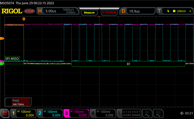
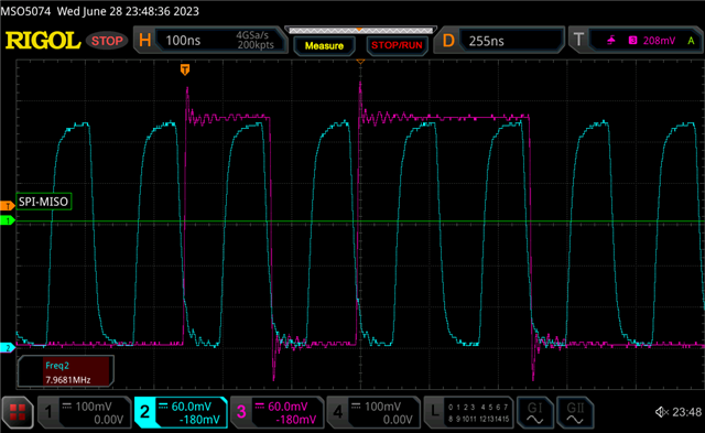
I have scoped the lines at 8, 16, and 32Mhz and they have essentially identical form. It does not seem to be raw signal related. I know the devices can work at 8Mhz because they work fine when using SPIM2. I tried using SPIM3 at 8Mhz and even down to 4Mhz and get the exact same behavior. So again, that leads me to believe that the issue is not speed or signal related, but that is just an assumption on my part.

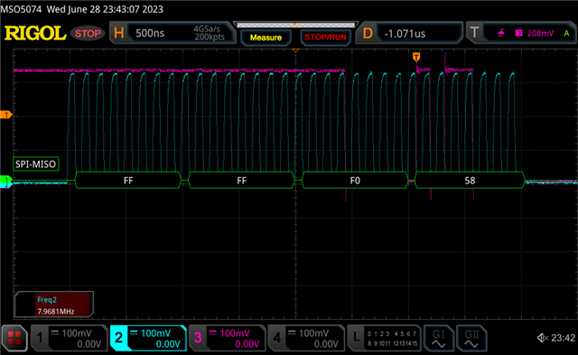
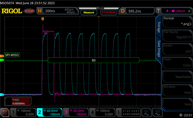
I also printed all of the spi traffic from the wifi module to see where things start to differ. It always differs at the exact same spot in configuration. It makes an 2 byte transmit and expects a 2 byte response of 0x00 0x58. I get the correct response when using SPIM2, but on SPIM3 it always responds with 0x00 0xb0. It may be a coincidence, but 0x58 left-bit-shifted by 1 is equal to 0xb0 so it may be that the RX value is being shifted to the left by one. (0x58 = 01011000; 0xb0 = 1011000).

I've read the various errata related to SPIM3 such as anomaly 198 and am working through ensuring that all relevant anomalies are being addressed.

Thank you for any advice or help,

Louis

Parents
  • Hello,

    So the first I would have checked is to make sure you have the correct phase and polarity:
    https://infocenter.nordicsemi.com/topic/ps_nrf52840/spim.html#register.CONFIG 

    I guess one could say that if that was the problem you should see the same for all spi interfaces, however the timing on the spim3 is faster relative to the edges, so it's not unlikely the problem was not seen on spim0-2.

    Kenneth

  • I had skipped checking that, but it appears I was lucky and was in the correct mode. NRF_SPIM3->CONFIG reports as 0 and the chip I have operates in mode 0 (CPHA = CPOL = 0) and the MSB is shifted first.

    Also, I know I had mentioned that I had scoped the signals, but I went a bit further and was actually decoding the MISO line and validated that while the chip's software was reporting a bit-shifted value (only after a certain point), the scope decoding was reading the correct values and the scope was also configured to use SPI mode 0.

  • Can you share some screenshots of the SPI transfer? E.g. first byte after CSN go low in specific.

    Kenneth

  • Sure, unfortunately for now I am limited to which signals I can probe because of our board size. I am measuring the SPI signals from the exposed pads for the cage that holds the SD card. For that reason I only have access to the CS pin for the SD card and do not have a way to probe the CS pin for the wifi module. This also means that I can't measure any SPI signals without removing the SD card (so no traffic happens).

    I do have one example of traffic with CS, MISO, and SCK when the board tries to first ask the SD card for info. Unfortunately, this is done at 250KHz due to the SD driver. Also since it is the first SPI transaction it wouldn't show what SPI was doing when I'm observing the problem.

    CS: yellow, MISO: purple, SCK: blue

    The rest of the examples I have are talking to the wifi module (since I know exactly what the traffic is supposed to be I can debug it). I can't probe that CS line but I do notice a difference in the signal when it works versus when it stops working.

    When it's working

    This is the first transaction with the wifi module. The decoded data is correct. The module and nordic are both configured for SPI mode 0, so I am sampling MISO on the CLK falling edge (threshold = 0.7*VDD).

    Visually, it looks like the clock falling edge roughly corresponds to a change in the data line (although it happens fairly close together).

    When it isn't working

    After a few transactions, I notice the data appears to be shifted (I know what the data should be based off looking at the transaction history taken using SPIM2).

    This data is incorrect now; the 0x80 decoded by the scope and also what the board software reports should be a 0x40. To reiterate, the scope and the board software are actually agreeing with each other. However, it now looks like the falling edge of CLK is perfectly in-between the data line transitioning. When the data was correct, they both transitioned at roughly the same time. So it looks to me like the timing between MISO and CLK shifts at some point which is what is shifting the data. If you sample that data on the rising edge instead then you get the correct value of 0x40 (but that wouldn't be SPI mode 0). I have confirmed that the SPI mode never changes according to the NRF_SPIM3->CONFIGURE register.

    Summary

    Just to make sure I haven't skipped something I can restate some things with the new info we have:

    • SPI2 @ 8MHz works great
    • SPI3 @ 8 MHz seems to get shifted after a few transactions
    • Both devices on the SPI line are affected after a certain amount of transactions
    • The scope configured to decode with the correct SPI mode agrees with what the software is seeing, but the data becomes shifted at some point

    Thanks for your help on this weird issue. I hope I've been clear in explaining the problem. I will try to think of a workaround for being able to measure the CS pin for the wifi module as your suspicion about CS timing does make sense with the timing between MISO and SCK becoming different (although I don't know why it would work at first and then stop working at the exact same point every time with either of the bus devices).

  • In case this is something you have not considered, SPIM3 AHB bus master has the lowest priority of all the peripherals, including SPIM2, a bit silly but then SPIM3 was a later addition. Also as a good general rule, avoid situations where more than one bus master is accessing the same slave.

    Worth a try: The RAM interface is divided into 9 RAM AHB slaves. RAM AHB slave 0-7 is connected to 2x4 kB RAM sections each and RAM AHB slave 8 is connected to 6x32 kB sections, as shown in Memory layout on page 20. Allocate one RAM section each to SPIM3 receive and SPIM3 transmit buffers, details on how to do this are sprinkled throughout the devzone. Other stuff (data) can reside in each of these two RAM sections, but they must not be frequently accessed by higher-speed peripherals which means none of the other peripherals as we've seen the SPIM3 is at the bottom of the barrel.

    I have run SPIM3 at maximum speed with no problems, but standalone, which would imply this is not a hardware bit error although the error here is hard to explain.

  • Two things to clarify the 'scope traces: 1) Adjust the compensation of each probe to square up the signals, usually a tiny screw on the probe head, and 2) offset the traces slightly so that the signal edges can be better viewed

  • With the screenshots above I see "working" is indeed Mode 0, shift on negative edge and sample on positive edge; however when it's "not working" the shift is occurring on the positive edge which implies either that the 'scope is showing traces from two different devices which have different Modes or that the device was inadvertently changed to use a different Mode.

    If two different devices with different modes just change the Mode prior to accessing each device.

Reply
  • With the screenshots above I see "working" is indeed Mode 0, shift on negative edge and sample on positive edge; however when it's "not working" the shift is occurring on the positive edge which implies either that the 'scope is showing traces from two different devices which have different Modes or that the device was inadvertently changed to use a different Mode.

    If two different devices with different modes just change the Mode prior to accessing each device.

Children
  • Yeah, I agree with you here. I'll double check to see what the mode for the other device is. I am however checking the NRF_SPIM3->CONFIG register on each transaction and it's always reporting as 0 which I was interpreting as the mode not changing. My understanding is that the mode is set through the spi_config struct by assigning the CPOL and CPHA values.

    I'm doing that in the device driver when I assign the bus to it:

    .spi = SPI_DT_SPEC_INST_GET(index,
    					    SPI_OP_MODE_MASTER |
    					    0 << 1 |                <--- CPOL
    					    0 << 2 |                <--- CPHA
    					    SPI_WORD_SET(8) |
    					    SPI_TRANSFER_MSB,
    					    0U),

    (I know shifting a 0 is pointless, but just for illustration)

    Edit: I have confirmed that both devices are being told to operate in mode 0.

    Thanks for your suggestions!

  • It's the slave on the "Not Working" device that is not in Mode 0, not the Master .. try changing the Mode on the Master just before accessing that fail case and all should be well

  • You should ideally measure both CLK, MISO and MOSI here. 

    It's only the MOSI that can show/confirm the correct mode is used every time by the SPI master, the MISO however is fully controlled by the slave device, and if MISO randomly change mode or polarity, then it's more likely a pin floating here somewhere that potentially cause the slave to change mode of operation than what you configure the SPI mode of the master.

    Kenneth

  • I agree with you, but it still leads to confusion since 2 independent spi devices have that same problem at the same time. In addition, the wifi chip is only capable of operating in one spi mode and there is no way to change it. This leads me to believe I could have measured the signals wrong or something.

    Also, I have a dev kit for the wifi module and hooked it up to an nrf52840DK where the only code / peripheral I was using was that single device and it works 9/10 times (1/10 times it fails in the same way as the production application on SPIM3 only).

    This leads me to believe that If I implement the suggestion by about explicitly allocating memory for the SPIM3 buffers I might have better results. Our production application is quite busy using a majority of the peripherals available. Putting it on the dev kit by itself seemed to help when only that single peripheral was being used.

    In addition, these SPI devices are the most important devices for our application, so learning that SPIM3 is the lowest priority peripheral might mean that the speed benefits are not worth it when many peripherals are being used simultaneously.

    Thanks for everyone's help. I will close this ticket for now since I think I have all the suggestions possible.

Related