TWI interface with flow sensor works incorrectly

Hello!

I have been trying to read a flow sensor with the nRF52840 DK, but the output is unexpected.

It has been proven that the flow sensor is functional, by connecting it with another MCU.

When I used a logic analyzer, the output I received was completely normal, meaning that the flow sensor is actually sending some values, and the DK receives them correctly. The thing is that the values that the flow sensor sends are incorrect. So, the flow sensor gives off incorrect values, but there is no problem with the DK.

After that, I tried to find what was wrong, and for the life of me, I could not see anything wrong with my code. As a result, I started all over from the TWI sensor example. Nothing changed. Even at the most basic level of TWI code, the registers I am reading are giving me the wrong info. What is curious is that when I use the same sensor with a BBB board, where I do not know and cannot change the code that is being executed, the flow sensor gives correct values. So it is not a sensor problem.

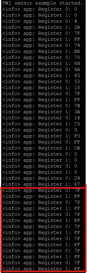
I am attaching you the twi code and the sensor's datasheet, where I have highlighted some lines on page 6, so you can understand a bit about the register I am trying to read. Chapter 2.4 is also quite useful. The sensor, by default, jumps into reading the flow register, and so I do not change the register read in my code. In the code, I am just shooting the sensor's flow registers values in the Terminal, every time a twi event occurs. I do not try to translate the data into real values, since I see that the raw register values are incorrect. The output of the code is shown in the figure. The red square contains the 7F-FF registers that denote the full-scale positive flow, which is totally incorrect, since I cannot produce such a flow (500LPM).

Do you have any idea what I am doing wrong?

I am truly pissed, because I know that it is a very simple application, but I cannot get it to work.

Thank you in advance,

Kostas

7723.twi_sensor_mine.zip4571.ESF Series I2C Interface_v2.pdf

Parents
  • Hi,

    I'd agree your code looks fine and it should be working. I didn't see any voltages mentioned on that data sheet - are you sure the logic levels on both MCUs are 3.3V like the Nordic?

    Other than that I would check the status register of the flow meter. If it seems to make sense and it reports an error, then you could try the reset command (0xFE). If signal decoding is actually being goofed then the status register shouldn't make sense and I'd still try that reset command.

Reply
  • Hi,

    I'd agree your code looks fine and it should be working. I didn't see any voltages mentioned on that data sheet - are you sure the logic levels on both MCUs are 3.3V like the Nordic?

    Other than that I would check the status register of the flow meter. If it seems to make sense and it reports an error, then you could try the reset command (0xFE). If signal decoding is actually being goofed then the status register shouldn't make sense and I'd still try that reset command.

Children
  • Hello again!

    Turns out, that I possessed an earlier version of the datasheet of the sensor and I worked with it on the 3.3V level.

    Now, I see that the updated version works at 5V of supply and gives an output of 0.5-4.5V. That means that the logic low is 0.5V and the logic high is 4.5V, right?

    Up till now, I had connected the flow sensor to the VDD pin, and it produced the output you saw in my last post. Is that logical? Moreover, now that I connected it to the 5V pin, the TWI does not generate any events and the communication is lost.

    If that is the case, and the sensor should work at the 5V level, how can I read the sensor at the different logic level?

    Thank you,

    Kostas

    P.S. I am attaching the other datasheet I found, if you would like to take anything from it.ESRF-ESF_V1.2.pdf

  • Yes, so the datasheet looks like it needs 5v supply (which you are giving it), but that also (PROBABLY) means that the I2C lines are working on 5V logic level. The nrf52840 can only operate on 1.8V and 3.3V logic levels. The GPIO pins on the nrf52840 (used for sda and scl signals) are not 5V tolerant, so having them hooked up can potentially damage the board / chip. I would stop testing with it until you get a converter so that you don't smoke the board.

    In order to use a device that has 5V logic level with the nrf52840, you need a 5V to 3.3V logic level converter. Here is a link to such a device. Once you have one of these, you would hook your flow meter up to the 5V pins on the converter and hook your nrf pins to the 3.3V pins on the converter. This will protect the nrf52840 and allow the two devices to talk.

    After you hook this up, if it still does not work, then try using different pins on the nordic than you have been using since the 5V signals could have damaged those pins on the nordic. If you want to check if they're damaged in advance, you can try configuring those pins as GPIO inputs and try applying a 3.3V signal to them and see if they correctly read as high and low.

    Good luck!

  • Also, the 0.4V - 4.5V mentioned is only if the sensor type was analog output, but yours is the I2c type.

    I'm not sure why it worked with the BBB board unless you had the 5V logic level cape for it.

  • Thank you very much nordicator!

    I will try the proposed steps and get back to you.

    Best regards,

    Kostas

  • Hey nordicator!

    You were totally right! It worked with the logic level converter! Thank you very much!

    One last question though, about the voltages.

    I am using a logic level converter which works between 5V and 3.3V. I have connected its high VDD pin to the 5V supply pin of the DK and its low VDD to the VDD pin of the DK, which is 3V. The low VDD of the logic level converter is recommended to be connected to a 3.3V supply though. Do you think, that there will be any problems in the data transfer, due to the supply not being 3.3V, but around 3V?

    Thank you again,

    Kostas

Related