I am trying to achieve +3dBm Tx power using VREQCTRL on the network core. I am currently executing the hex on normal voltage mode. I am unable to distinguish the power levels between 0 dBm and +3 dBm hexes using RSSI viewer on nRF connect app (iOS) (values at specific distances are more or less identical).
I have the following questions:
Power supply questions:
- Is a normal voltage mode, capped at 1.8V supply voltage (VDD) sufficient?
- Does VREGRADIO powering the network core internally does a DC/DC voltage boost on VREQH request.
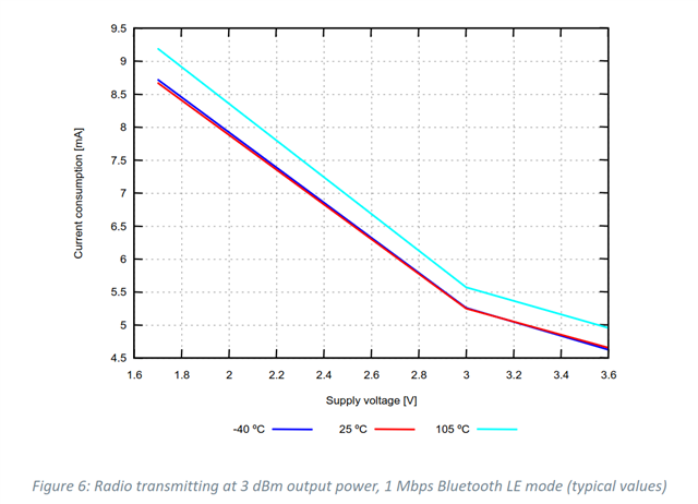
- I also found a graph (attached) suggested 1.8V supply is sufficient for +3 dBm. Please confirm correctness.
Testing questions:
- The RSSI viewer (on nRF Connect App using an iPhone) shows -12 to -16 dBm for both 0 and +3 dBm firmwares which is the cause of contention.
- Is this a correct observation?
- How accurate are the RSSI viewers?
- Does the hardware running (in this case iPhone) makes a difference?
- Does the environment (we didn't test in a special chamber) make a difference?
- Will a spectrum analyzer help with this issue or will it have the same observations?
Thanks !
Attached:
- Source code
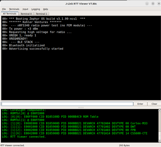
- RTT observation
- Graph for +3 dBm
#include <stdbool.h>
#include <stdlib.h>
#include <string.h>

#include <zephyr/sys/printk.h>
#include <zephyr/sys/byteorder.h>

#include <zephyr/init.h>
#include <zephyr/types.h>

#include <hal/nrf_power.h>

// Create test firmware for BLE or Radio stack.
#define BLE_STACK true
// Create firmwares for 0 dBM or 3 dBm.
#define THREE_DBM false

#if BLE_STACK
// Add BLE stack related headers here.
#include <zephyr/bluetooth/bluetooth.h>
#include <zephyr/bluetooth/hci.h>
#include <zephyr/bluetooth/hci_vs.h>
#include <zephyr/bluetooth/conn.h>
#include <zephyr/bluetooth/uuid.h>
#include <zephyr/bluetooth/gatt.h>
#include <zephyr/settings/settings.h>
#else
#include <zephyr/drivers/clock_control.h>
#include <zephyr/drivers/clock_control/nrf_clock_control.h>
#include "radio_test.h"
#endif

// Device Name.
#if THREE_DBM
#define DEVICE_NAME "pos3dBm_BLE_radio_test"
#else
#define DEVICE_NAME "0dBm_BLE_radio_test"
#endif
#define DEVICE_NAME_LEN (sizeof(DEVICE_NAME) - 1)

#if BLE_STACK
static const struct bt_data ad[] =
    {
        BT_DATA_BYTES(BT_DATA_FLAGS, (BT_LE_AD_GENERAL | BT_LE_AD_NO_BREDR)),
        BT_DATA(BT_DATA_NAME_COMPLETE, DEVICE_NAME, DEVICE_NAME_LEN),
};

static const struct bt_data sd[] =
    {
        BT_DATA(BT_DATA_NAME_COMPLETE, DEVICE_NAME, DEVICE_NAME_LEN),
};

static void connected(struct bt_conn *conn, uint8_t err)
{
    if (err)
    {
        printk("Connection failed (err %u)\n", err);
        return;
    }
    printk("Connected\n");
}

static void disconnected(struct bt_conn *conn, uint8_t reason)
{
    printk("Disconnected (reason %u)\n", reason);
}

BT_CONN_CB_DEFINE(conn_callbacks) =
    {
        .connected = connected,
        .disconnected = disconnected,
};

#else
static void clock_init(void)
{
    int err;
    int res;
    struct onoff_manager *clk_mgr;
    struct onoff_client clk_cli;

    clk_mgr = z_nrf_clock_control_get_onoff(CLOCK_CONTROL_NRF_SUBSYS_HF);
    if (!clk_mgr)
    {
        printk("Unable to get the Clock manager\n");
        return;
    }

    sys_notify_init_spinwait(&clk_cli.notify);

    err = onoff_request(clk_mgr, &clk_cli);
    if (err < 0)
    {
        printk("Clock request failed: %d\n", err);
        return;
    }

    do
    {
        err = sys_notify_fetch_result(&clk_cli.notify, &res);
        if (!err && res)
        {
            printk("Clock could not be started: %d\n", res);
            return;
        }
    } while (err);

    printk("Clock has started\n");
}

static void tx_modulated_carrier_end(void)
{
    printk("The modulated TX packet transmission complete.\n");
}
#endif

/*
    RADIO POWER ENHANCEMENT.
    Voltage Control to achieve power beyond 0 dBm.
    Read more in README.md file.
    https://infocenter.nordicsemi.com/index.jsp?topic=%2Fps_nrf5340%2Fchapters%2Fvreqctrl%2Fdoc%2Fvreqctrl.html&anchor=frontpage
*/
#if THREE_DBM
void radio_power_enhance(void)
{
    printk("Requesting high voltage for radio ...\r\n");
    NRF_VREQCTRL->VREGRADIO.VREQH = 1;
    while (!NRF_VREQCTRL->VREGRADIO.VREQHREADY)
        ;
    printk("VREQH %d, ready %d\n", NRF_VREQCTRL->VREGRADIO.VREQH, NRF_VREQCTRL->VREGRADIO.VREQHREADY);
    printk("VREQHREADY!\r\n");
}
#endif

// --- MAIN FUNCTION ---
void main(void)
{
    printk("******* Kohler Ventures *******\r\n");
    printk(" --- nRF5340 radio power test (no FEM module) ---\r\n");
    printk("Tx power : ");
#if THREE_DBM
    printk("+3 dBm\r\n");
    radio_power_enhance();
#else
    printk("0 dBm\r\n");
#endif

#if BLE_STACK
    /* BLE STACK
     * Initialize and Enable BLE for connection
     */
    printk(" --- BLE STACK ---\r\n");
    int err;

    err = bt_enable(NULL);
    if (err)
    {
        printk("[ERROR] Bluetooth init failed (err %d)\n", err);
        return;
    }
    printk("Bluetooth initialized\n");

    err = bt_le_adv_start(BT_LE_ADV_CONN, ad, ARRAY_SIZE(ad), sd, ARRAY_SIZE(sd));
    if (err)
    {
        printk("[ERROR] Advertising failed to start (err %d)\n", err);
        return;
    }
    printk("Advertising successfully started\n");

    while (1)
    {
        k_sleep(K_SECONDS(1));
    }

#else
    /* RADIO TEST
     * Continuous BLE packet transmission on the Tx.
     */
    printk(" --- RADIO TEST STACK ---\r\n");

    clock_init();

    /* Radio parameter configuration. */
    struct radio_param_config
    {
        enum transmit_pattern tx_pattern;
        nrf_radio_mode_t mode;
        uint8_t txpower;
        uint8_t channel_start;
        uint8_t channel_end;
        uint32_t delay_ms;
        uint32_t duty_cycle;

#if CONFIG_FEM
        /* Front-end module (FEM) configuration. */
        struct radio_test_fem fem;
#endif /* CONFIG_FEM */
    };

    // Radio Config Parameters.
    struct radio_param_config config =
    {
        .tx_pattern = TRANSMIT_PATTERN_11110000,
        .mode = NRF_RADIO_MODE_BLE_2MBIT,
        .txpower = RADIO_TXPOWER_TXPOWER_0dBm,
        .channel_start = 40,
        .channel_end = 60,
        .delay_ms = 50,
        .duty_cycle = 50,
#if CONFIG_FEM
        .fem.gain = FEM_USE_DEFAULT_GAIN
#endif /* CONFIG_FEM */
    };

    // Initialize Radio
    struct radio_test_config test_config;
    if (radio_test_init(&test_config) == 0)
        printk("Radio Initialized.\r\n");
    else
        printk("[ERROR] Radio Initialization.\r\n");

    // Set Test Configs.
    memset(&test_config, 0, sizeof(test_config));
    test_config.type = MODULATED_TX;
    test_config.mode = config.mode;

    test_config.params.modulated_tx.channel = config.channel_start;
    test_config.params.modulated_tx.txpower = config.txpower;
    test_config.params.modulated_tx.pattern = config.tx_pattern;
    test_config.params.modulated_tx.packets_num = 0;
    test_config.params.modulated_tx.cb = tx_modulated_carrier_end;

    // Start Radio.
    radio_test_start(&test_config);
    printk("Radio Transmission Started. \r\n");
#endif
}


