Hello,
I am trying to access I2C device - onboard Holyiot 21061 board. When setting in DT the compatibility to "nordic,nrf-twim" - I2C isn't able to communicate with a device. I do not have an analyser, but all APIs return -EIO.
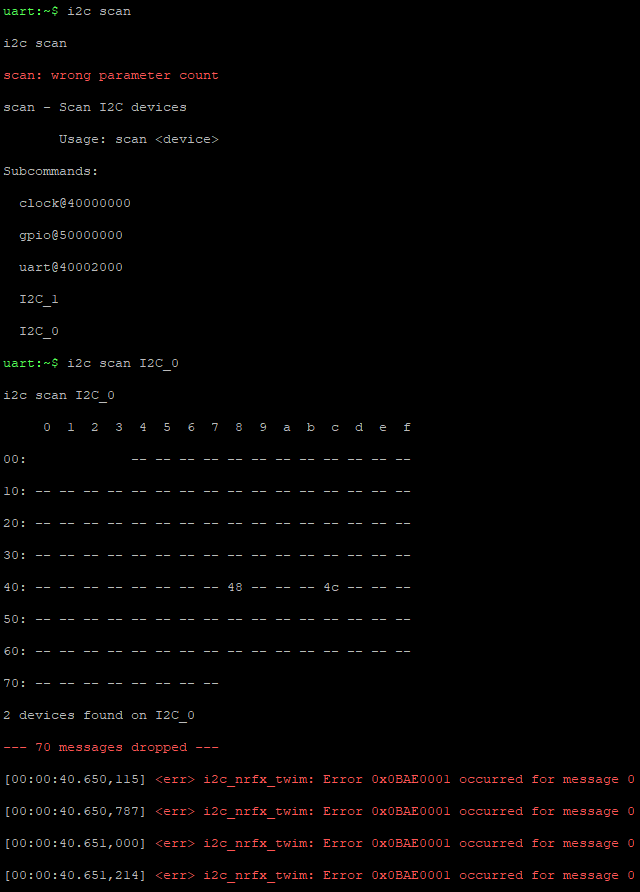
In the output of I2C shell "i2c scan" command - no devices are found. But when I change the compatibility to "nordic, nr-twi" (w/o trailing "m") - everything works OK.
/dts-v1/;
#include <nordic/nrf52832_qfaa.dtsi>
#include "holyiot_21061-pinctrl.dtsi"

/ {
	model = "Holyiot 21061";
	compatible = "holyiot,21061";

	chosen {
		zephyr,console = &uart0;
		zephyr,shell-uart = &uart0;
		zephyr,uart-mcumgr = &uart0;
		zephyr,bt-mon-uart = &uart0;
		zephyr,bt-c2h-uart = &uart0;
		zephyr,sram = &sram0;
		zephyr,flash = &flash0;
		zephyr,code-partition = &slot0_partition;
	};

	leds {
		compatible = "gpio-leds";
		led0: led_0 {
			gpios = <&gpio0 0 GPIO_ACTIVE_HIGH>;
			label = "LED0";
		};
		led1: led_1 {
			gpios = <&gpio0 1 GPIO_ACTIVE_HIGH>;
			label = "LED1";
		};
		led2: led_2 {
			gpios = <&gpio0 2 GPIO_ACTIVE_HIGH>;
			label = "LED2";
		};
	};

	/* These aliases are provided for compatibility with samples */
	aliases {
		ledr = &led0;
		ledg = &led1;
		ledb = &led2;
		watchdog0 = &wdt0;
	};
};

&gpio0 {
	status = "okay";

	pin_as_output_low {
		gpio-hog;
		gpios = <30 GPIO_ACTIVE_HIGH>, <1 GPIO_ACTIVE_HIGH>, <27 GPIO_ACTIVE_HIGH>; // VDD_EN
		output-low; /* or output-low */
		line-name = "pin_as_output_low";
	};

	pin_as_output_high {
		gpio-hog;
		gpios = <5 GPIO_ACTIVE_HIGH>; // Ad0 & CS
		output-high; /* or output-low */
		line-name = "pin_as_output_high";
	};

};

&gpiote {
	status = "okay";
};


&flash0 {

	partitions {
		compatible = "fixed-partitions";
		#address-cells = <1>;
		#size-cells = <1>;

		boot_partition: partition@0 {
			label = "mcuboot";
			reg = <0x00000000 0xc000>;
		};
		slot0_partition: partition@c000 {
			label = "image-0";
			reg = <0x0000C000 0x37000>;
		};
		slot1_partition: partition@43000 {
			label = "image-1";
			reg = <0x00043000 0x37000>;
		};
		storage_partition: partition@7a000 {
			label = "storage";
			reg = <0x0007a000 0x00006000>;
		};
	};
};

i2c0: &i2c0 {
	status = "okay";
	compatible = "nordic,nrf-twi";
	pinctrl-names = "default", "sleep";
	pinctrl-0 = <&i2c0_default>;
	pinctrl-1 = <&i2c0_sleep>;
	label = "I2C_0";

};

i2c1: &i2c1 {
	status = "okay";
	compatible = "nordic,nrf-twi";
	pinctrl-names = "default", "sleep";
	pinctrl-0 = <&i2c1_default>;
	pinctrl-1 = <&i2c1_sleep>;
	label = "I2C_1";

};
&pinctrl {
	i2c0_default: i2c0_default {
		group1 {
			psels = <NRF_PSEL(TWIM_SDA, 0, 3)>,
				<NRF_PSEL(TWIM_SCL, 0, 4)>;
		};
	};

	i2c0_sleep: i2c0_sleep {
		group1 {
			psels = <NRF_PSEL(TWIM_SDA, 0, 3)>,
				<NRF_PSEL(TWIM_SCL, 0, 4)>;
			low-power-enable;
		};
	};
	i2c1_default: i2c1_default {
		group1 {
			psels = <NRF_PSEL(TWIM_SDA, 0, 26)>,
				<NRF_PSEL(TWIM_SCL, 0, 25)>;
		};
	};

	i2c1_sleep: i2c1_sleep {
		group1 {
			psels = <NRF_PSEL(TWIM_SDA, 0, 26)>,
				<NRF_PSEL(TWIM_SCL, 0, 25)>;
			low-power-enable;
		};
	};
};
CONFIG_GPIO=y
CONFIG_GPIO_HOGS=y

CONFIG_SHELL=y
CONFIG_SHELL_BACKEND_RTT=y

# choose RTT console
CONFIG_USE_SEGGER_RTT=y
CONFIG_CONSOLE=y
CONFIG_RTT_CONSOLE=y

# General config
CONFIG_LOG=y
CONFIG_LOG_PRINTK=y

CONFIG_I2C=y
CONFIG_NRFX_GPIOTE=y
CONFIG_I2C_NRFX=y
Please advise (main() function is just an endless loop of k_msleep(1000))