I'm prototyping with a nRF9160 DK using nRF Connect SDK v2.4.0 and the Visual Code extension. I'm using an ADXL372z breakout board that I want to communicate with via SPI. When I've done this in the past using an nRF52840DK, the same ADXL372 breakout board and SDK 17, I have had to configure the GPIO pins used for SCLK and MOSI with NRF_GPIO_PIN_H0H1. I've also had to keep the clock frequency below 1MHz. This is because the jumper wire lengths between the DK and the breakout board make you need a bit more current than normal. Also without using twisted pair wiring with proper grounding, you have to keep line frequencies low.
short ADXL372_spi_master_init(nrf_drv_spi_t m_spi0_master,
                              nrf_drv_spi_evt_handler_t spi_event_handler,
                              bool *xferdone)
{
    uint32_t              err_code = 0;

    m_ad_spi_master = m_spi0_master;

    m_config.ss_pin       = NRF_DRV_SPI_PIN_NOT_USED;
    m_config.irq_priority = APP_IRQ_PRIORITY_LOW;
    m_config.orc          = 0xFF;  // Most devices expect ones as filler/dummy bytes.
    m_config.frequency    = NRF_SPI_FREQ_8M;
    m_config.mode         = NRF_DRV_SPI_MODE_0;  // Corresponds to the datasheet specification CPHA = CPOL = 0
    m_config.bit_order    = NRF_DRV_SPI_BIT_ORDER_MSB_FIRST;  // Put it out the way you put it in

    m_config.sck_pin  = SPI_SCK_PIN;
    m_config.mosi_pin = SPI_MOSI_PIN;
    m_config.miso_pin = SPI_MISO_PIN;

    err_code = nrf_drv_spi_init(&m_ad_spi_master, &m_config, spi_event_handler, NULL);
    APP_ERROR_CHECK(err_code);

    #if (USING_DEVELOPMENT_KIT == 1)
    nrf_gpio_cfg(SPI_SCK_PIN,
                 NRF_GPIO_PIN_DIR_OUTPUT,
                 NRF_GPIO_PIN_INPUT_DISCONNECT,
                 NRF_GPIO_PIN_NOPULL,
                 NRF_GPIO_PIN_H0H1,
                 NRF_GPIO_PIN_NOSENSE);

    nrf_gpio_cfg(SPI_MOSI_PIN,
                 NRF_GPIO_PIN_DIR_OUTPUT,
                 NRF_GPIO_PIN_INPUT_DISCONNECT,
                 NRF_GPIO_PIN_NOPULL,
                 NRF_GPIO_PIN_H0H1,
                 NRF_GPIO_PIN_NOSENSE);
    #endif // (USING_DEVELOPMENT_KIT == 1)

    spixferdone = xferdone;
    m_spi_event_handler = spi_event_handler;

    return (0);

}
This works for prototyping under SDK 17.
I need to do the same using nRF Connect SDK. I can't figure out where to use NRF_GPIO_DRIVE_H0H1 because I don't know how to configure individual GPIO pins under Zephyr. This is my current overlay file:
// To get started, press Ctrl+Space to bring up the completion menu and view the available nodes.
// For more help, browse the DeviceTree documentation at https: //docs.zephyrproject.org/latest/guides/dts/index.html
//
//


&pinctrl
{

    spi3_default: spi3_default
	{
	    group1
		{
		    psels = <NRF_PSEL(SPIM_SCK, 0, 0)>,
				    <NRF_PSEL(SPIM_MOSI, 0, 1)>,
				    <NRF_PSEL(SPIM_MISO, 0, 2)>;

	    };
    };

    spi3_sleep: spi3_sleep
	{
	    group2
		{
		    psels = <NRF_PSEL(SPIM_SCK, 0, 0)>,
				    <NRF_PSEL(SPIM_MOSI, 0, 1)>,
				    <NRF_PSEL(SPIM_MISO, 0, 2)>;
		    low-power-enable;
	    };
	};
};


/*** link SPI pin configurations with a device ***/
my_spi3: &spi3
{
	compatible = "nordic,nrf-spim";
	status = "okay";
	pinctrl-0 = <&spi3_default>;
	pinctrl-1 = <&spi3_sleep>;
	pinctrl-names = "default", "Sleep";
	cs-gpios = <&gpio0 4 GPIO_ACTIVE_LOW>, <&gpio0 29 GPIO_ACTIVE_LOW>;

	winbondflash: flash@0
	{
		compatible = "winbond,w25n01", "jedec,spi-nor";
		size = <1073741824>;
		reg = <0>;
		label = "1GBIT_FLASH_DEVICE";
		spi-max-frequency = <1000000>;
		jedec-id = [ EF AA 21  ];	//UNIQUE TO SPECIFIC FLASH CHIP BEING USED W25N01G
	};

	adxl372: spi-dev-adxl372@1
	{
		compatible = "adi,adxl372";
		spi-max-frequency = <1000000>;
		reg = <1>;
		int1-gpios = <&gpio0 19 0>;
	};


};
This is my initialization and use
#include "spi3.h"
#include <zephyr/kernel.h>
#include <zephyr/drivers/gpio.h>
#include <zephyr/drivers/pwm.h>
#include <zephyr/drivers/spi.h>
#include <zephyr/logging/log.h>

struct spi_cs_control adxl372_spi_cs =
{
	.gpio = SPI_CS_GPIOS_DT_SPEC_GET(DT_NODELABEL(adxl372)),
	.delay = 0,
};


static const struct spi_config adxl372_spi3_cfg =
{
	.operation = SPI_WORD_SET(8) | SPI_TRANSFER_MSB |
				 SPI_OP_MODE_MASTER | SPI_MODE_CPOL | SPI_MODE_CPHA,
	.frequency = 400000,
	.slave = 0,
	.cs = &adxl372_spi_cs,
};

struct spi_cs_control winbond1g_spi_cs =
{
	.gpio = SPI_CS_GPIOS_DT_SPEC_GET(DT_NODELABEL(winbondflash)),
	.delay = 0,
};


static const struct spi_config winbond1g_spi3_cfg =
{
	.operation = SPI_WORD_SET(8) | SPI_TRANSFER_MSB |
				 SPI_OP_MODE_MASTER | SPI_MODE_CPOL | SPI_MODE_CPHA,
	.frequency = 400000,
	.slave = 0,
	.cs = &winbond1g_spi_cs,
};

static const struct device *spi3_dev;

uint8_t init_spi3(void)
{
	int      err;

	spi3_dev = DEVICE_DT_GET(DT_NODELABEL(spi3));

    if (spi3_dev == NULL)
    {
		printk("Could not get %s device\n", spi3_dev->name);
        return 1;
    }
	printk("SPI Device: %s\n", spi3_dev->name);

    return 0;
}


int adxl372_id(void)
{
	static uint8_t tx_buffer[2];
	static uint8_t rx_buffer[2];

	const struct spi_buf tx_buf =
	{
		.buf = tx_buffer,
		.len = sizeof(tx_buffer)
	};
	const struct spi_buf_set tx =
	{
		.buffers = &tx_buf,
		.count = 1
	};

	struct spi_buf rx_buf =
	{
		.buf = rx_buffer,
		.len = sizeof(rx_buffer),
	};
	const struct spi_buf_set rx =
	{
		.buffers = &rx_buf,
		.count = 1
	};


	// last byte of rx contains the response from the accelerometer
    // Shift the register's address to the left by one, inorder to
    // clear bit 0, and set bit 0 high per the adxl372 data sheet's
    // specification for the read command structure of the device's SPI Protocal.

	tx_buffer[0] = (0x02 << 1) + 1;

	int error = spi_transceive(spi3_dev, &adxl372_spi3_cfg, &tx, &rx);
	if (error != 0)
	{
		printk("SPI transceive error: %i\n", error);
		return error;
	}

	if(rx_buffer[1] == 0xfa)
	{
		printk("Successfull ACC communication\n");
	}
	else
	{
		printk("Faild ACC communication\n");
		printk("SPI Tx bytes: ");
		for (int i = 0; i < sizeof(tx_buffer); i++)
		{
			printk("%x ", tx_buffer[i]);
		}
		printk(" SPI Rx bytes: ");
		for (int i = 0; i < sizeof(rx_buffer); i++)
		{
			printk("%x ", rx_buffer[i]);
		}
		printk("\n");
	}

	return 0;
}
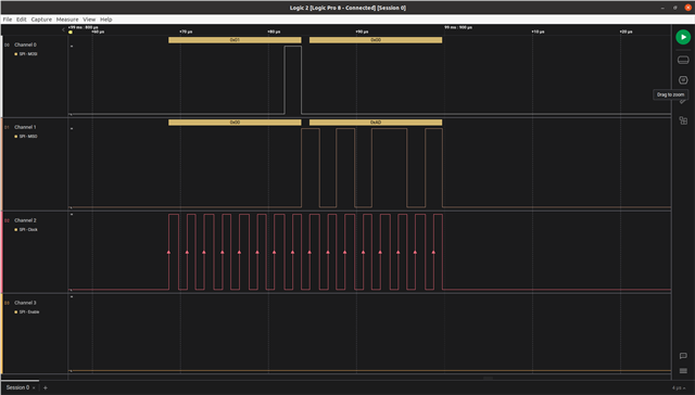
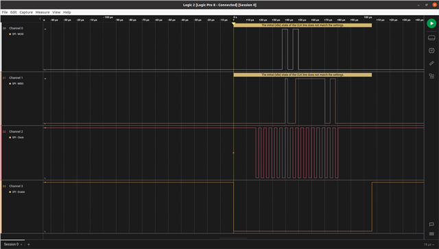
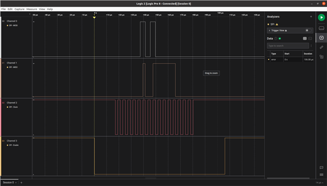
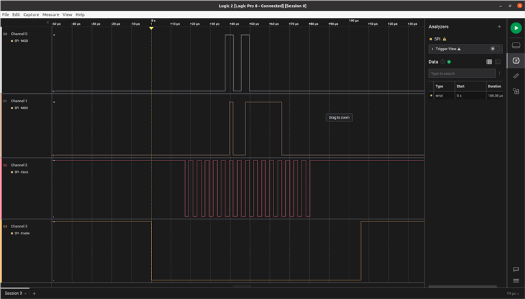
This is a screen shot of the adxl372_id function in action (
How do I configure the GPIO pins I'm using for SCLK and MOSI to be NRF_GPIO_PIN_H0H1 ? Should I do that GPIO configuration in my Overlay file and how would I do that?
Why is my clock line normally high ?
Greatly appreciate any help and advice. Thank you.