How to program an external board using a DK board?

Before I start, I beg that any responses do NOT link to any other threads. There are 20 threads across the internet in different forums documenting how they got external programming to work, but the biggest issue is that they're all different, and use different boards. For example, my version of the nRF52840 DK doesn't even have the 'GND DETECT' pin that's listed in the very documentation for the board.

This area is massively lacking, and following the official documentation, I've bricked two external boards... not impressed.

I have two boards, an itsy bitsy nRF52840 Express and an nRF52840 DK. I'm using Zephyr Project RTOS, but I'm using 'Programmer' in 'nRF Connect for Desktop' to actually upload through the DK board to the itsy bitsy.

My connections are as follows:

DK              |         Itsy Bitsy

GND          -->      GND

VDD nRF   -->      VDD

SWDIO      -->      SWDIO

SCLK         -->      SCLK

The programmer says it's complete, but the itsy bitsy doesn't seem to be doing what I programmed it to do (output HIGH on pin 10).

The concerning part is that holding the RST or SW pins on the itsy bitsy no longer trigger the bootloader mode (though this could be because I erased any bootloaders in uploading using the DK board).

I'm totally lost, developing with nRF chips just feels like chasing one senseless issue after another.

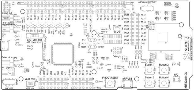
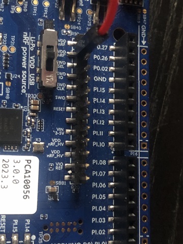
The nRF52840 DK pinout below, which is in the official documentation does NOT match the pinout I see on my board, which I will post below the other image.
Parents
  • Hello,

    I am sorry for the frustration. I see that you are using the latest version of the DK, which again changed the names of these pins, apparently. 

    The queue here is that the debugger doesn't power your external device (Itsy Bitsy). It rather checks whether it can detect the already powered device, and if it does, it will use the P20 header (from your picture) instead of programming the nRF52840 on the DK itself. 

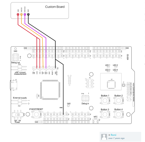
    This is why you see this picture a lot in these kind of posts:

    What it tells you is that you need to both power the Itsy Bitsy, by connecting VDD and GND from the DK to the custom board, and then you need to connect VTG* and GND DETECt to VDD and GND respectively, at the same time as the external board needs to be powered. 

    In the version that you are using, the GND detect has been removed, and the VTG has changed the name to SWD_SEL. So what you need to do is to make sure the Itsy Bitsy is powered (e.g. by connecting it to GND and VDD), and then you need to connect SWD_SEL to VDD as well. When SWD_SEL is set high, that will trigger the onboard debugger to use the P20 debug out port. Then all you need to do is to connect SWD_CLK and SWD_IO, which are the logic signals actually used to program the Itsy Bitsy.

    Try that, and let me know if it doesn't help.

    Best regards,

    Edvin

Reply
  • Hello,

    I am sorry for the frustration. I see that you are using the latest version of the DK, which again changed the names of these pins, apparently. 

    The queue here is that the debugger doesn't power your external device (Itsy Bitsy). It rather checks whether it can detect the already powered device, and if it does, it will use the P20 header (from your picture) instead of programming the nRF52840 on the DK itself. 

    This is why you see this picture a lot in these kind of posts:

    What it tells you is that you need to both power the Itsy Bitsy, by connecting VDD and GND from the DK to the custom board, and then you need to connect VTG* and GND DETECt to VDD and GND respectively, at the same time as the external board needs to be powered. 

    In the version that you are using, the GND detect has been removed, and the VTG has changed the name to SWD_SEL. So what you need to do is to make sure the Itsy Bitsy is powered (e.g. by connecting it to GND and VDD), and then you need to connect SWD_SEL to VDD as well. When SWD_SEL is set high, that will trigger the onboard debugger to use the P20 debug out port. Then all you need to do is to connect SWD_CLK and SWD_IO, which are the logic signals actually used to program the Itsy Bitsy.

    Try that, and let me know if it doesn't help.

    Best regards,

    Edvin

Children
No Data
Related