
Hi All,
I am trying to test a single WS2812B led wired to the GPIO 3 of my nrf9160 custom board (designed by someone else), I would like to use the PWM driver as I am unable to build the led_ws2812 sample since the nrf9160 is not supported.
Here it seems that this LED can be controlled with nrf9160 and PWM via GPIO. I am able to build and flash my board with the rgb_led basic sample however the led on my board do not turn on. I am not sure if this is a hardware or software error. I program my board with a J-Link EDU Mini via SWD pins and the board is connected to a 3.7v power supply, the LED does turn on if I directly connect it to the power supply.
I also use the NRF connect SDK 2.4.1 with VS code.
I am very new to nrf connect and followed the instructions I could find in the documentation here. Any help would be greatly appreciated.
Best wishes
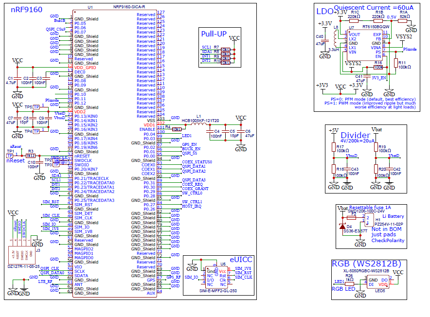
My custom pcb schematic
myboard.dts
// Copyright (c) 2023 Nordic Semiconductor ASA
// SPDX-License-Identifier: Apache-2.0

/dts-v1/;
#include <nordic/nrf9160_sica.dtsi>

/ {
	model = "myboard";
	compatible = "nordic,myboard";

	chosen {
		zephyr,sram = &sram0;
		zephyr,flash = &flash0;
		zephyr,code-partition = &slot0_partition;
	};

};


&flash0 {
	partitions {
		compatible = "fixed-partitions";
		#address-cells = <1>;
		#size-cells = <1>;

		boot_partition: partition@0 {
			label = "mcuboot";
			reg = <0x0 0x10000>;
		};
		slot0_partition: partition@10000 {
			label = "image-0";
			reg = <0x10000 0x40000>;
		};
		slot0_ns_partition: partition@50000 {
			label = "image-0-nonsecure";
			reg = <0x50000 0x30000>;
		};
		slot1_partition: partition@80000 {
			label = "image-1";
			reg = <0x80000 0x40000>;
		};
		slot1_ns_partition: partition@c0000 {
			label = "image-1-nonsecure";
			reg = <0xc0000 0x30000>;
		};
		scratch_partition: partition@f0000 {
			label = "image-scratch";
			reg = <0xf0000 0xa000>;
		};
		storage_partition: partition@fa000 {
			label = "storage";
			reg = <0xfa000 0x6000>;
		};
	};
};
myboard.overlay
// To get started, press Ctrl+Space to bring up the completion menu and view the available nodes.

// You can also use the buttons in the sidebar to perform actions on nodes.
// Actions currently available include:

// * Enabling / disabling the node
// * Adding the bus to a bus
// * Removing the node
// * Connecting ADC channels

// For more help, browse the DeviceTree documentation at https://docs.zephyrproject.org/latest/guides/dts/index.html
// You can also visit the nRF DeviceTree extension documentation at https://nrfconnect.github.io/vscode-nrf-connect/devicetree/nrfdevicetree.html


/ {
    aliases {
        red-pwm-led = &pwm_led0;
        green-pwm-led = &pwm_led1;
        blue-pwm-led = &pwm_led2;
    };

    pwmleds0 {
        compatible = "pwm-leds";
        status = "okay";

        pwm_led0: led_pwm_0 {
                status = "okay";
                pwms = <&pwm0 0 PWM_MSEC(1) PWM_POLARITY_NORMAL>;
                label = "LED0 red";
        };

        pwm_led1: led_pwm_1 {
                status = "okay";
                pwms = <&pwm0 1 PWM_MSEC(1) PWM_POLARITY_NORMAL>;
                label = "LED0 green";
        };

        pwm_led2: led_pwm_2 {
                status = "okay";
                pwms = <&pwm0 2 PWM_MSEC(1) PWM_POLARITY_NORMAL>;
                label = "LED0 blue";
        };
    };
};


&gpio0 {
	status = "okay";
};

&pinctrl {
    pwm0_default_alt: pwm0_default_alt {
            group1 {
                    psels = <NRF_PSEL(PWM_OUT0, 0, 3)>;
            };
    };

    pwm0_sleep_alt: pwm0_sleep_alt {
            group1 {
                    psels = <NRF_PSEL(PWM_OUT0, 0, 3)>;
            };
    };
};

&pwm0 {
    status = "okay";
    pinctrl-0 = <&pwm0_default_alt>;
    pinctrl-1 = <&pwm0_sleep_alt>;
    pinctrl-names = "default", "sleep";
};
prj.conf
CONFIG_PRINTK=y
CONFIG_PWM=y
CONFIG_LOG=y

CONFIG_GPIO=y
CONFIG_LED=y
CONFIG_SERIAL=y
CONFIG_CONSOLE=y

CONFIG_USE_SEGGER_RTT=y
CONFIG_RTT_CONSOLE=y
CONFIG_UART_CONSOLE=n
CONFIG_PINCTRL=y
CONFIG_NRFX_GPIOTE=y
CONFIG_NRFX_PWM0=y
main.c
/*
 * Copyright (c) 2016 Intel Corporation
 *
 * SPDX-License-Identifier: Apache-2.0
 */

/**
 * @file Sample app to demonstrate PWM-based RGB LED control
 */

#include <zephyr/kernel.h>
#include <zephyr/sys/printk.h>
#include <zephyr/device.h>
#include <zephyr/drivers/pwm.h>

static const struct pwm_dt_spec red_pwm_led =
	PWM_DT_SPEC_GET(DT_ALIAS(red_pwm_led));
static const struct pwm_dt_spec green_pwm_led =
	PWM_DT_SPEC_GET(DT_ALIAS(green_pwm_led));
static const struct pwm_dt_spec blue_pwm_led =
	PWM_DT_SPEC_GET(DT_ALIAS(blue_pwm_led));

#define STEP_SIZE PWM_USEC(2000)

int main(void)
{
	uint32_t pulse_red, pulse_green, pulse_blue; /* pulse widths */
	int ret;

	printk("PWM-based RGB LED control\n");

	if (!device_is_ready(red_pwm_led.dev) ||
	    !device_is_ready(green_pwm_led.dev) ||
	    !device_is_ready(blue_pwm_led.dev)) {
		printk("Error: one or more PWM devices not ready\n");
		return 0;
	}

	printk("okay\n");

	while (1) {
		for (pulse_red = 0U; pulse_red <= red_pwm_led.period;
		     pulse_red += STEP_SIZE) {
			ret = pwm_set_pulse_dt(&red_pwm_led, pulse_red);
			if (ret != 0) {
				printk("Error %d: red write failed\n", ret);
				return 0;
			}

			for (pulse_green = 0U;
			     pulse_green <= green_pwm_led.period;
			     pulse_green += STEP_SIZE) {
				ret = pwm_set_pulse_dt(&green_pwm_led,
						       pulse_green);
				if (ret != 0) {
					printk("Error %d: green write failed\n",
					       ret);
					return 0;
				}

				for (pulse_blue = 0U;
				     pulse_blue <= blue_pwm_led.period;
				     pulse_blue += STEP_SIZE) {
					ret = pwm_set_pulse_dt(&blue_pwm_led,
							       pulse_blue);
					if (ret != 0) {
						printk("Error %d: "
						       "blue write failed\n",
						       ret);
						return 0;
					}
					k_sleep(K_SECONDS(1));
				}
			}
		}
	}
	return 0;
}
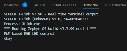
RTT output
build log trace


