Working with Adafruit 2.8" capacitive touch display not working with nRF9160-DK

Hi,

I am working with an Adafruit display 2.8" capacitive. The display is working when I flash lvgl sample and hat attached to nRF52840-dk. But it does not work with nRF9160-DK.

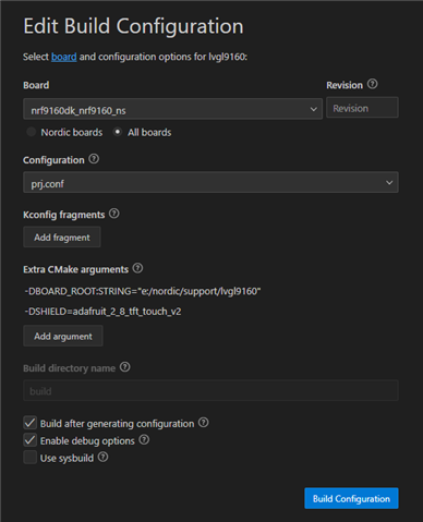
I changed some of the required pins in the device tree of the board. The configurations are as follows in the boards directory of nRF9160-DK

arduino_spi: &spi3 {
compatible = "nordic,nrf-spim";
status = "okay";
cs-gpios = <&arduino_header 16 GPIO_ACTIVE_LOW>; /* D10 */
pinctrl-0 = <&spi3_default>;
pinctrl-1 = <&spi3_sleep>;
pinctrl-names = "default", "sleep";
};

Inside the pin control file, it looks like the following.

spi3_default: spi3_default {
group1 {
psels = <NRF_PSEL(SPIM_SCK, 0, 13)>,
<NRF_PSEL(SPIM_MOSI, 0, 11)>,
<NRF_PSEL(SPIM_MISO, 0, 12)>;
};
};

spi3_sleep: spi3_sleep {
group1 {
psels = <NRF_PSEL(SPIM_SCK, 0, 13)>,
<NRF_PSEL(SPIM_MOSI, 0, 11)>,
<NRF_PSEL(SPIM_MISO, 0, 12)>;
low-power-enable;
};
};

https://learn.adafruit.com/adafruit-2-8-tft-touch-shield-v2/connecting

Then I also looked at the shields field. There is the following configuration for the device arduino_spi.

Which should work in my undestanding. 

&arduino_spi {

status = "okay";
cs-gpios = <&arduino_header 16 GPIO_ACTIVE_LOW>, /* D10 */
<&arduino_header 10 GPIO_ACTIVE_LOW>; /* D04 */


ili9340: ili9340@0 {
compatible = "ilitek,ili9340";
label = "ILI9340";
spi-max-frequency = <15151515>;
reg = <0>;
cmd-data-gpios = <&arduino_header 15 GPIO_ACTIVE_LOW>; /* D9 */
width = <320>;
height = <240>;
pixel-format = <ILI9XXX_PIXEL_FORMAT_RGB888>;
rotation = <90>;
frmctr1 = [00 18];
pwctrl1 = [23 00];
vmctrl1 = [3e 28];
vmctrl2 = [86];
pgamctrl = [0f 31 2b 0c 0e 08 4e f1 37 07 10 03 0e 09 00];
ngamctrl = [00 0e 14 03 11 07 31 c1 48 08 0f 0c 31 36 0f];
};

sdhc0: sdhc@1 {
compatible = "zephyr,mmc-spi-slot";
reg = <1>;
status = "okay";
label = "SDHC0";
spi-max-frequency = <24000000>;
};
};

What I am not sure is that could be that there is nRF52840 SoC on this board which is used for various board control and pin control functions. So maybe that could be missing.

Parents
  • Hi Ujjval, 

    Do your project compile or does it give you an error during runtime? It would be great it you could post the logs and your prj.conf

    Regards

    Runar

  • Hi,

    Yes, my project compiles without error.

    However, when I flash I do get an error but still it works on nRF52840.

    Here is the prj.conf

    CONFIG_LV_Z_MEM_POOL_NUMBER_BLOCKS=8
    CONFIG_MAIN_STACK_SIZE=2048
    #CONFIG_HEAP_MEM_POOL_SIZE=2048
    
    CONFIG_DISPLAY=y
    CONFIG_DISPLAY_LOG_LEVEL_ERR=y
    
    CONFIG_LOG=y
    
    CONFIG_LVGL=y
    CONFIG_LV_MEM_CUSTOM=y
    CONFIG_LV_USE_LOG=y
    CONFIG_LV_USE_LABEL=y
    CONFIG_LV_USE_BTN=y
    CONFIG_LV_USE_IMG=y
    CONFIG_LV_FONT_MONTSERRAT_14=y
    
    CONFIG_SRAM_SIZE=256
    CONFIG_BOOTLOADER_SRAM_SIZE=256

    The error is following for both the boards,

    [00:00:02.351,379] <err> lvgl: Could put input data into queue
    [00:00:02.361,419] <err> lvgl: Could put input data into queue
    [00:00:02.364,410] <wrn> lvgl: (2.364, +31) indev_pointer_proc: X is 320 which is greater than hor. res (in lv_indev.c line #347)

  • Hi Ujjval. 

    Is that the complied zephyr.dts from your build folder? Could you upload the overlay file you created? I rather not go through 800 lines and not knowing if you have an overlay file that override it. 

    Also, anything reagarding where it crashes? Without a shield I need something to start with. 

    Regards

    Runar

  • Hi Runar,

    Unfortunately, I don't have right debugger setup so that I could look what's going wrong exactly.

    I do not have an overlay of my own. So there will be everything zephyr.dts file. Only I am using is the node named &arduino_spi and &arduino_i2c

  • If you don't have an overlay. Where did you then set up the device tree for display?

    If you are using a nRF9160dk then you have an debugger on the DK

    Modify your build configuration like this:

    Then starta  debug session

    And 

    Regards

    Runar

  • Hi Runar,

    I do not have VS code installed with all the required things for dubugging. It works but it breaks in the meantime. Also, regarding the overlay file, I have updated the corresponding .dts files in /arm/boards directory of my Zephyr installation.

    I normally use command line to flash to the board, with -- -DSHILD option selected while building.

    So for debugging I recently download the Ozone for that, and could set breakpoints and see all other debug functionalities. The Code works normally with "CPU running" status and do not show any error.

    I do not know yet...I am relatively new to debugging with software.

  • I think that the pinconfiguration could be wrong as I may have to change the nRF52840 board control to enable the SPI. As the following picture mentions that there is external flash connected to this same SPI interface I am using.

    These are pins P0.13/12/11 for SPI clock, and data. So maybe I will try to enable that and then I think CS pin will take care to select the right slave.

Reply
  • I think that the pinconfiguration could be wrong as I may have to change the nRF52840 board control to enable the SPI. As the following picture mentions that there is external flash connected to this same SPI interface I am using.

    These are pins P0.13/12/11 for SPI clock, and data. So maybe I will try to enable that and then I think CS pin will take care to select the right slave.

Children
No Data
Related