Connecting nRF9160DK and nRF7002DK for testing SCAN sample.

Dear team,

I am trying to test Wi-Fi scan sample with the kits nRF9160DK and nRF7002DK. I am aware of nRF7002-EK and it is taking time to get it. Since we are running out of time, we are trying to accomplish the same using previously said two DKs.

In the hardware,

I saw the ticket  nRF9160 and nRF7002 Wi-Fi controller connection and made the following connections.

Board nRF9160-DK(P3 & P4) nRF7002-DK (P24)
SPI CLK P0.13 P0.17
SPI CS P0.10 P0.18
SPI MOSI P0.11 P0.13
SPI MISO P0.12 P0.14
HOST-IRQ  P0.07 P0.23
IOVDD-CTR  P0.00 P0.31
BUCKEN P0.01 P0.12

Also I soldered the SBs from SB20 to SB25 on nRF7002DK.

I DID NOT remove the 0R Resistors R26-R31.

I powered both DKs seperately using USB cables.

Now, the firmware part.

I programmed nRF5340 on nRF7002 DK with basic blinky, to make sure it is not using any other GPIOs, that we are using.

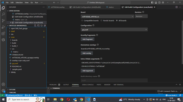
Now, I opened the Wi-Fi Scan sample in VS Code.

Toolchain used is v2.4.1.

I added the overlay-scan-only.conf, nrf9160dk_nrf9160_ns.overlay under boards.

I added -DSHIELD:STRING="nrf7002ek" and -DOVERLAY_CONFIG=overlay-scan-only.conf under CMake arguments in build configuration.

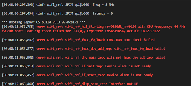
Build is successful, but when programmed, no UART output is seen.

Please help.

Thanks a ton in advance.

  • Hello Hakon,

    Here is the zephyr.dts file.

    /dts-v1/;
    
    / {
    	#address-cells = < 0x1 >;
    	#size-cells = < 0x1 >;
    	model = "Nordic nRF9160 DK NRF9160";
    	compatible = "nordic,nrf9160-dk-nrf9160";
    	chosen {
    		zephyr,entropy = &psa_rng;
    		zephyr,flash-controller = &flash_controller;
    		zephyr,console = &uart0;
    		zephyr,shell-uart = &uart0;
    		zephyr,uart-mcumgr = &uart0;
    		zephyr,flash = &flash0;
    		zephyr,sram = &sram0_ns;
    		zephyr,code-partition = &slot0_ns_partition;
    	};
    	aliases {
    		led0 = &led0;
    		led1 = &led1;
    		led2 = &led2;
    		led3 = &led3;
    		pwm-led0 = &pwm_led0;
    		sw0 = &button0;
    		sw1 = &button1;
    		sw2 = &button2;
    		sw3 = &button3;
    		bootloader-led0 = &led0;
    		mcuboot-button0 = &button0;
    		mcuboot-led0 = &led0;
    		watchdog0 = &wdt0;
    	};
    	soc {
    		#address-cells = < 0x1 >;
    		#size-cells = < 0x1 >;
    		compatible = "nordic,nRF9160-SICA", "nordic,nRF9160", "nordic,nRF91", "simple-bus";
    		interrupt-parent = < &nvic >;
    		ranges;
    		nvic: interrupt-controller@e000e100 {
    			#address-cells = < 0x1 >;
    			compatible = "arm,v8m-nvic";
    			reg = < 0xe000e100 0xc00 >;
    			interrupt-controller;
    			#interrupt-cells = < 0x2 >;
    			arm,num-irq-priority-bits = < 0x3 >;
    			phandle = < 0x1 >;
    		};
    		systick: timer@e000e010 {
    			compatible = "arm,armv8m-systick";
    			reg = < 0xe000e010 0x10 >;
    			status = "disabled";
    		};
    		sram0: memory@20000000 {
    			compatible = "mmio-sram";
    			reg = < 0x20000000 0x40000 >;
    		};
    		peripheral@40000000 {
    			#address-cells = < 0x1 >;
    			#size-cells = < 0x1 >;
    			ranges = < 0x0 0x40000000 0x10000000 >;
    			flash_controller: flash-controller@39000 {
    				compatible = "nordic,nrf91-flash-controller";
    				reg = < 0x39000 0x1000 >;
    				partial-erase;
    				#address-cells = < 0x1 >;
    				#size-cells = < 0x1 >;
    				flash0: flash@0 {
    					compatible = "soc-nv-flash";
    					erase-block-size = < 0x1000 >;
    					write-block-size = < 0x4 >;
    					reg = < 0x0 0x100000 >;
    					partitions {
    						compatible = "fixed-partitions";
    						#address-cells = < 0x1 >;
    						#size-cells = < 0x1 >;
    						boot_partition: partition@0 {
    							label = "mcuboot";
    							reg = < 0x0 0x10000 >;
    						};
    						slot0_partition: partition@10000 {
    							label = "image-0";
    							reg = < 0x10000 0x40000 >;
    						};
    						slot0_ns_partition: partition@50000 {
    							label = "image-0-nonsecure";
    							reg = < 0x50000 0x30000 >;
    						};
    						slot1_partition: partition@80000 {
    							label = "image-1";
    							reg = < 0x80000 0x40000 >;
    						};
    						slot1_ns_partition: partition@c0000 {
    							label = "image-1-nonsecure";
    							reg = < 0xc0000 0x30000 >;
    						};
    						storage_partition: partition@f8000 {
    							label = "storage";
    							reg = < 0xf8000 0x8000 >;
    						};
    					};
    				};
    			};
    			adc: adc@e000 {
    				compatible = "nordic,nrf-saadc";
    				reg = < 0xe000 0x1000 >;
    				interrupts = < 0xe 0x1 >;
    				status = "okay";
    				#io-channel-cells = < 0x1 >;
    				phandle = < 0x12 >;
    			};
    			dppic: dppic@17000 {
    				compatible = "nordic,nrf-dppic";
    				reg = < 0x17000 0x1000 >;
    				status = "okay";
    			};
    			egu0: egu@1b000 {
    				compatible = "nordic,nrf-egu";
    				reg = < 0x1b000 0x1000 >;
    				interrupts = < 0x1b 0x1 >;
    				status = "okay";
    			};
    			egu1: egu@1c000 {
    				compatible = "nordic,nrf-egu";
    				reg = < 0x1c000 0x1000 >;
    				interrupts = < 0x1c 0x1 >;
    				status = "okay";
    			};
    			egu2: egu@1d000 {
    				compatible = "nordic,nrf-egu";
    				reg = < 0x1d000 0x1000 >;
    				interrupts = < 0x1d 0x1 >;
    				status = "okay";
    			};
    			egu3: egu@1e000 {
    				compatible = "nordic,nrf-egu";
    				reg = < 0x1e000 0x1000 >;
    				interrupts = < 0x1e 0x1 >;
    				status = "okay";
    			};
    			egu4: egu@1f000 {
    				compatible = "nordic,nrf-egu";
    				reg = < 0x1f000 0x1000 >;
    				interrupts = < 0x1f 0x1 >;
    				status = "okay";
    			};
    			egu5: egu@20000 {
    				compatible = "nordic,nrf-egu";
    				reg = < 0x20000 0x1000 >;
    				interrupts = < 0x20 0x1 >;
    				status = "okay";
    			};
    			ipc: ipc@2a000 {
    				compatible = "nordic,nrf-ipc";
    				reg = < 0x2a000 0x1000 >;
    				interrupts = < 0x2a 0x1 >;
    				status = "okay";
    			};
    			i2s0: i2s@28000 {
    				compatible = "nordic,nrf-i2s";
    				#address-cells = < 0x1 >;
    				#size-cells = < 0x0 >;
    				reg = < 0x28000 0x1000 >;
    				interrupts = < 0x28 0x1 >;
    				status = "disabled";
    			};
    			kmu: kmu@39000 {
    				compatible = "nordic,nrf-kmu";
    				reg = < 0x39000 0x1000 >;
    				interrupts = < 0x39 0x1 >;
    				status = "okay";
    			};
    			pdm0: pdm@26000 {
    				compatible = "nordic,nrf-pdm";
    				reg = < 0x26000 0x1000 >;
    				interrupts = < 0x26 0x1 >;
    				status = "disabled";
    			};
    			regulators: regulator@4000 {
    				compatible = "nordic,nrf-regulators";
    				reg = < 0x4000 0x1000 >;
    				status = "okay";
    			};
    			vmc: vmc@3a000 {
    				compatible = "nordic,nrf-vmc";
    				reg = < 0x3a000 0x1000 >;
    				status = "okay";
    			};
    			uart0: uart@8000 {
    				compatible = "nordic,nrf-uarte";
    				reg = < 0x8000 0x1000 >;
    				interrupts = < 0x8 0x1 >;
    				status = "okay";
    				current-speed = < 0x1c200 >;
    				pinctrl-0 = < &uart0_default >;
    				pinctrl-1 = < &uart0_sleep >;
    				pinctrl-names = "default", "sleep";
    			};
    			uart1: arduino_serial: uart@9000 {
    				compatible = "nordic,nrf-uarte";
    				reg = < 0x9000 0x1000 >;
    				interrupts = < 0x9 0x1 >;
    				status = "disabled";
    				current-speed = < 0x1c200 >;
    				pinctrl-0 = < &uart1_default >;
    				pinctrl-1 = < &uart1_sleep >;
    				pinctrl-names = "default", "sleep";
    			};
    			uart2: uart@a000 {
    				compatible = "nordic,nrf-uarte";
    				reg = < 0xa000 0x1000 >;
    				interrupts = < 0xa 0x1 >;
    				status = "disabled";
    				pinctrl-0 = < &uart2_default >;
    				pinctrl-1 = < &uart2_sleep >;
    				pinctrl-names = "default", "sleep";
    			};
    			uart3: uart@b000 {
    				compatible = "nordic,nrf-uarte";
    				reg = < 0xb000 0x1000 >;
    				interrupts = < 0xb 0x1 >;
    				status = "disabled";
    			};
    			i2c0: i2c@8000 {
    				compatible = "nordic,nrf-twim";
    				#address-cells = < 0x1 >;
    				#size-cells = < 0x0 >;
    				reg = < 0x8000 0x1000 >;
    				clock-frequency = < 0x186a0 >;
    				interrupts = < 0x8 0x1 >;
    				status = "disabled";
    			};
    			i2c1: i2c@9000 {
    				compatible = "nordic,nrf-twim";
    				#address-cells = < 0x1 >;
    				#size-cells = < 0x0 >;
    				reg = < 0x9000 0x1000 >;
    				clock-frequency = < 0x186a0 >;
    				interrupts = < 0x9 0x1 >;
    				status = "disabled";
    			};
    			i2c2: arduino_i2c: i2c@a000 {
    				compatible = "nordic,nrf-twim";
    				#address-cells = < 0x1 >;
    				#size-cells = < 0x0 >;
    				reg = < 0xa000 0x1000 >;
    				clock-frequency = < 0x186a0 >;
    				interrupts = < 0xa 0x1 >;
    				status = "okay";
    				pinctrl-0 = < &i2c2_default >;
    				pinctrl-1 = < &i2c2_sleep >;
    				pinctrl-names = "default", "sleep";
    			};
    			i2c3: i2c@b000 {
    				compatible = "nordic,nrf-twim";
    				#address-cells = < 0x1 >;
    				#size-cells = < 0x0 >;
    				reg = < 0xb000 0x1000 >;
    				clock-frequency = < 0x186a0 >;
    				interrupts = < 0xb 0x1 >;
    				status = "disabled";
    			};
    			spi0: spi@8000 {
    				compatible = "nordic,nrf-spim";
    				#address-cells = < 0x1 >;
    				#size-cells = < 0x0 >;
    				reg = < 0x8000 0x1000 >;
    				interrupts = < 0x8 0x1 >;
    				max-frequency = < 0x7a1200 >;
    				easydma-maxcnt-bits = < 0xd >;
    				status = "disabled";
    			};
    			spi1: spi@9000 {
    				compatible = "nordic,nrf-spim";
    				#address-cells = < 0x1 >;
    				#size-cells = < 0x0 >;
    				reg = < 0x9000 0x1000 >;
    				interrupts = < 0x9 0x1 >;
    				max-frequency = < 0x7a1200 >;
    				easydma-maxcnt-bits = < 0xd >;
    				status = "disabled";
    			};
    			spi2: spi@a000 {
    				compatible = "nordic,nrf-spim";
    				#address-cells = < 0x1 >;
    				#size-cells = < 0x0 >;
    				reg = < 0xa000 0x1000 >;
    				interrupts = < 0xa 0x1 >;
    				max-frequency = < 0x7a1200 >;
    				easydma-maxcnt-bits = < 0xd >;
    				status = "disabled";
    			};
    			spi3: arduino_spi: spi@b000 {
    				compatible = "nordic,nrf-spim";
    				#address-cells = < 0x1 >;
    				#size-cells = < 0x0 >;
    				reg = < 0xb000 0x1000 >;
    				interrupts = < 0xb 0x1 >;
    				max-frequency = < 0x7a1200 >;
    				easydma-maxcnt-bits = < 0xd >;
    				status = "okay";
    				cs-gpios = < &arduino_header 0x10 0x1 >;
    				pinctrl-0 = < &spi3_default >;
    				pinctrl-1 = < &spi3_sleep >;
    				pinctrl-names = "default", "sleep";
    				nrf700x: nrf7002@0 {
    					compatible = "nordic,nrf700x-spi";
    					status = "okay";
    					reg = < 0x0 >;
    					spi-max-frequency = < 0x7a1200 >;
    					iovdd-ctrl-gpios = < &arduino_header 0x6 0x20 >;
    					bucken-gpios = < &arduino_header 0x7 0x20 >;
    					host-irq-gpios = < &arduino_header 0xd 0x0 >;
    				};
    			};
    			pwm0: pwm@21000 {
    				compatible = "nordic,nrf-pwm";
    				reg = < 0x21000 0x1000 >;
    				interrupts = < 0x21 0x1 >;
    				status = "okay";
    				#pwm-cells = < 0x3 >;
    				pinctrl-0 = < &pwm0_default >;
    				pinctrl-1 = < &pwm0_sleep >;
    				pinctrl-names = "default", "sleep";
    				phandle = < 0x10 >;
    			};
    			pwm1: pwm@22000 {
    				compatible = "nordic,nrf-pwm";
    				reg = < 0x22000 0x1000 >;
    				interrupts = < 0x22 0x1 >;
    				status = "disabled";
    				#pwm-cells = < 0x3 >;
    			};
    			pwm2: pwm@23000 {
    				compatible = "nordic,nrf-pwm";
    				reg = < 0x23000 0x1000 >;
    				interrupts = < 0x23 0x1 >;
    				status = "disabled";
    				#pwm-cells = < 0x3 >;
    			};
    			pwm3: pwm@24000 {
    				compatible = "nordic,nrf-pwm";
    				reg = < 0x24000 0x1000 >;
    				interrupts = < 0x24 0x1 >;
    				status = "disabled";
    				#pwm-cells = < 0x3 >;
    			};
    			gpio0: gpio@842500 {
    				compatible = "nordic,nrf-gpio";
    				gpio-controller;
    				reg = < 0x842500 0x300 >;
    				#gpio-cells = < 0x2 >;
    				status = "okay";
    				port = < 0x0 >;
    				phandle = < 0xf >;
    			};
    			rtc0: rtc@14000 {
    				compatible = "nordic,nrf-rtc";
    				reg = < 0x14000 0x1000 >;
    				cc-num = < 0x4 >;
    				interrupts = < 0x14 0x1 >;
    				status = "disabled";
    				clock-frequency = < 0x8000 >;
    				prescaler = < 0x1 >;
    			};
    			rtc1: rtc@15000 {
    				compatible = "nordic,nrf-rtc";
    				reg = < 0x15000 0x1000 >;
    				cc-num = < 0x4 >;
    				interrupts = < 0x15 0x1 >;
    				status = "disabled";
    				clock-frequency = < 0x8000 >;
    				prescaler = < 0x1 >;
    			};
    			clock: clock@5000 {
    				compatible = "nordic,nrf-clock";
    				reg = < 0x5000 0x1000 >;
    				interrupts = < 0x5 0x1 >;
    				status = "okay";
    			};
    			power: power@5000 {
    				compatible = "nordic,nrf-power";
    				reg = < 0x5000 0x1000 >;
    				interrupts = < 0x5 0x1 >;
    				status = "okay";
    				#address-cells = < 0x1 >;
    				#size-cells = < 0x1 >;
    				gpregret1: gpregret1@551c {
    					compatible = "nordic,nrf-gpregret";
    					reg = < 0x551c 0x1 >;
    					status = "okay";
    				};
    				gpregret2: gpregret2@5520 {
    					compatible = "nordic,nrf-gpregret";
    					reg = < 0x5520 0x1 >;
    					status = "okay";
    				};
    			};
    			wdt: wdt0: watchdog@18000 {
    				compatible = "nordic,nrf-wdt";
    				reg = < 0x18000 0x1000 >;
    				interrupts = < 0x18 0x1 >;
    				status = "okay";
    			};
    			timer0: timer@f000 {
    				compatible = "nordic,nrf-timer";
    				status = "disabled";
    				reg = < 0xf000 0x1000 >;
    				cc-num = < 0x6 >;
    				max-bit-width = < 0x20 >;
    				interrupts = < 0xf 0x1 >;
    				prescaler = < 0x0 >;
    			};
    			timer1: timer@10000 {
    				compatible = "nordic,nrf-timer";
    				status = "disabled";
    				reg = < 0x10000 0x1000 >;
    				cc-num = < 0x6 >;
    				max-bit-width = < 0x20 >;
    				interrupts = < 0x10 0x1 >;
    				prescaler = < 0x0 >;
    			};
    			timer2: timer@11000 {
    				compatible = "nordic,nrf-timer";
    				status = "disabled";
    				reg = < 0x11000 0x1000 >;
    				cc-num = < 0x6 >;
    				max-bit-width = < 0x20 >;
    				interrupts = < 0x11 0x1 >;
    				prescaler = < 0x0 >;
    			};
    		};
    		gpiote: gpiote@40031000 {
    			compatible = "nordic,nrf-gpiote";
    			reg = < 0x40031000 0x1000 >;
    			interrupts = < 0x31 0x5 >;
    			status = "okay";
    		};
    	};
    	pinctrl: pin-controller {
    		compatible = "nordic,nrf-pinctrl";
    		uart0_default: uart0_default {
    			phandle = < 0x2 >;
    			group1 {
    				psels = < 0x1d >, < 0x2001b >;
    			};
    			group2 {
    				psels = < 0x1001c >, < 0x3001a >;
    				bias-pull-up;
    			};
    		};
    		uart0_sleep: uart0_sleep {
    			phandle = < 0x3 >;
    			group1 {
    				psels = < 0x1d >, < 0x1001c >, < 0x2001b >, < 0x3001a >;
    				low-power-enable;
    			};
    		};
    		uart1_default: uart1_default {
    			phandle = < 0x4 >;
    			group1 {
    				psels = < 0x1 >, < 0x2000e >;
    			};
    			group2 {
    				psels = < 0x10000 >, < 0x3000f >;
    				bias-pull-up;
    			};
    		};
    		uart1_sleep: uart1_sleep {
    			phandle = < 0x5 >;
    			group1 {
    				psels = < 0x1 >, < 0x10000 >, < 0x2000e >, < 0x3000f >;
    				low-power-enable;
    			};
    		};
    		uart2_default: uart2_default {
    			phandle = < 0x6 >;
    			group1 {
    				psels = < 0x18 >, < 0x10017 >;
    			};
    		};
    		uart2_sleep: uart2_sleep {
    			phandle = < 0x7 >;
    			group1 {
    				psels = < 0x18 >, < 0x10017 >;
    				low-power-enable;
    			};
    		};
    		i2c2_default: i2c2_default {
    			phandle = < 0x8 >;
    			group1 {
    				psels = < 0xc001e >, < 0xb001f >;
    			};
    		};
    		i2c2_sleep: i2c2_sleep {
    			phandle = < 0x9 >;
    			group1 {
    				psels = < 0xc001e >, < 0xb001f >;
    				low-power-enable;
    			};
    		};
    		pwm0_default: pwm0_default {
    			phandle = < 0xd >;
    			group1 {
    				psels = < 0x160002 >;
    			};
    		};
    		pwm0_sleep: pwm0_sleep {
    			phandle = < 0xe >;
    			group1 {
    				psels = < 0x160002 >;
    				low-power-enable;
    			};
    		};
    		spi3_default: spi3_default {
    			phandle = < 0xb >;
    			group1 {
    				psels = < 0x4000d >, < 0x6000c >, < 0x5000b >;
    				nordic,drive-mode = < 0x3 >;
    			};
    		};
    		spi3_sleep: spi3_sleep {
    			phandle = < 0xc >;
    			group1 {
    				psels = < 0x4000d >, < 0x6000c >, < 0x5000b >;
    				low-power-enable;
    			};
    		};
    	};
    	rng_hci: entropy_bt_hci {
    		compatible = "zephyr,bt-hci-entropy";
    		status = "okay";
    	};
    	cpus {
    		#address-cells = < 0x1 >;
    		#size-cells = < 0x0 >;
    		cpu@0 {
    			device_type = "cpu";
    			compatible = "arm,cortex-m33f";
    			reg = < 0x0 >;
    			#address-cells = < 0x1 >;
    			#size-cells = < 0x1 >;
    			mpu: mpu@e000ed90 {
    				compatible = "arm,armv8m-mpu";
    				reg = < 0xe000ed90 0x40 >;
    				arm,num-mpu-regions = < 0x10 >;
    			};
    		};
    	};
    	psa_rng: psa-rng {
    		compatible = "zephyr,psa-crypto-rng";
    		status = "okay";
    	};
    	leds {
    		compatible = "gpio-leds";
    		led0: led_0 {
    			gpios = < &gpio0 0x2 0x0 >;
    			label = "Green LED 1";
    		};
    		led1: led_1 {
    			gpios = < &gpio0 0x3 0x0 >;
    			label = "Green LED 2";
    		};
    		led2: led_2 {
    			gpios = < &gpio0 0x4 0x0 >;
    			label = "Green LED 3";
    		};
    		led3: led_3 {
    			gpios = < &gpio0 0x5 0x0 >;
    			label = "Green LED 4";
    		};
    	};
    	pwmleds {
    		compatible = "pwm-leds";
    		pwm_led0: pwm_led_0 {
    			pwms = < &pwm0 0x0 0x1312d00 0x0 >;
    		};
    	};
    	buttons {
    		compatible = "gpio-keys";
    		button0: button_0 {
    			gpios = < &gpio0 0x6 0x11 >;
    			label = "Push button 1";
    		};
    		button1: button_1 {
    			gpios = < &gpio0 0x7 0x11 >;
    			label = "Push button 2";
    		};
    		button2: button_2 {
    			gpios = < &gpio0 0x8 0x11 >;
    			label = "Switch 1";
    		};
    		button3: button_3 {
    			gpios = < &gpio0 0x9 0x11 >;
    			label = "Switch 2";
    		};
    	};
    	interface_to_nrf52840: gpio-interface {
    		compatible = "nordic,nrf9160dk-nrf52840-interface";
    		#gpio-cells = < 0x2 >;
    		gpio-map-mask = < 0xf 0x0 >;
    		gpio-map-pass-thru = < 0x0 0xffffffff >;
    		gpio-map = < 0x0 0x0 &gpio0 0x11 0x0 >, < 0x1 0x0 &gpio0 0x12 0x0 >, < 0x2 0x0 &gpio0 0x13 0x0 >, < 0x3 0x0 &gpio0 0x15 0x0 >, < 0x4 0x0 &gpio0 0x16 0x0 >, < 0x5 0x0 &gpio0 0x17 0x0 >;
    		phandle = < 0x11 >;
    	};
    	nrf52840_reset: gpio-reset {
    		compatible = "nordic,nrf9160dk-nrf52840-reset";
    		status = "disabled";
    		gpios = < &interface_to_nrf52840 0x5 0x0 >;
    	};
    	arduino_header: connector {
    		compatible = "arduino-header-r3";
    		#gpio-cells = < 0x2 >;
    		gpio-map-mask = < 0xffffffff 0xffffffc0 >;
    		gpio-map-pass-thru = < 0x0 0x3f >;
    		gpio-map = < 0x0 0x0 &gpio0 0xe 0x0 >, < 0x1 0x0 &gpio0 0xf 0x0 >, < 0x2 0x0 &gpio0 0x10 0x0 >, < 0x3 0x0 &gpio0 0x11 0x0 >, < 0x4 0x0 &gpio0 0x12 0x0 >, < 0x5 0x0 &gpio0 0x13 0x0 >, < 0x6 0x0 &gpio0 0x0 0x0 >, < 0x7 0x0 &gpio0 0x1 0x0 >, < 0x8 0x0 &gpio0 0x2 0x0 >, < 0x9 0x0 &gpio0 0x3 0x0 >, < 0xa 0x0 &gpio0 0x4 0x0 >, < 0xb 0x0 &gpio0 0x5 0x0 >, < 0xc 0x0 &gpio0 0x6 0x0 >, < 0xd 0x0 &gpio0 0x7 0x0 >, < 0xe 0x0 &gpio0 0x8 0x0 >, < 0xf 0x0 &gpio0 0x9 0x0 >, < 0x10 0x0 &gpio0 0xa 0x0 >, < 0x11 0x0 &gpio0 0xb 0x0 >, < 0x12 0x0 &gpio0 0xc 0x0 >, < 0x13 0x0 &gpio0 0xd 0x0 >, < 0x14 0x0 &gpio0 0x1e 0x0 >, < 0x15 0x0 &gpio0 0x1f 0x0 >;
    		phandle = < 0xa >;
    	};
    	arduino_adc: analog-connector {
    		compatible = "arduino,uno-adc";
    		#io-channel-cells = < 0x1 >;
    		io-channel-map = < 0x0 &adc 0x1 >, < 0x1 &adc 0x2 >, < 0x2 &adc 0x3 >, < 0x3 &adc 0x4 >, < 0x4 &adc 0x5 >, < 0x5 &adc 0x6 >;
    	};
    	reserved-memory {
    		#address-cells = < 0x1 >;
    		#size-cells = < 0x1 >;
    		ranges;
    		sram0_s: image_s@20000000 {
    			reg = < 0x20000000 0x16000 >;
    		};
    		sram0_modem: image_modem@20016000 {
    			reg = < 0x20016000 0xa000 >;
    		};
    		sram0_ns: image_ns@20020000 {
    			reg = < 0x20020000 0x20000 >;
    		};
    	};
    	nrf_radio_coex: nrf7002-coex {
    		status = "okay";
    		compatible = "nordic,nrf700x-coex";
    		status0-gpios = < &arduino_header 0x8 0x0 >;
    		req-gpios = < &arduino_header 0x9 0x0 >;
    		grant-gpios = < &arduino_header 0xa 0x21 >;
    		swctrl1-gpios = < &arduino_header 0xc 0x0 >;
    	};
    };
    

    Also, can we have nRF9160 in STA mode using nRF7002? Why is it available only for scanning in SDK?

  • Hakon,

    Sorry, there was a mistake in sharing the dts file. I have edited the previous reply and now it is correct. Sorry for the mistake.

    Thanks.

  • Hi,


    I took one of my nRF7002-DK v1.0.2, soldered SB20-25 and connected according to your setup:

    Board nRF9160-DK(P3 & P4) nRF7002-DK (P24)
    SPI CLK P0.13 P0.17
    SPI CS P0.10 P0.18
    SPI MOSI P0.11 P0.13
    SPI MISO P0.12 P0.14
    HOST-IRQ  P0.07 P0.23
    IOVDD-CTR  P0.00 P0.31
    BUCKEN P0.01 P0.12

    I used a nRF9160-DK v1.0.0

    Took the samples/wifi/scan sample, and configured/compiled it with:

    west build -b nrf9160dk_nrf9160_ns -- -DSHIELD=nrf7002ek


    And here's the output:

    [00:00:00.416,931] <inf> wifi_nrf: SPIM spi@b000: freq = 8 MHz
    
    [00:00:00.416,992] <inf> wifi_nrf: SPIM spi@b000: latency = 0
    
    [00:00:00.500,213] <inf> wifi_nrf: Firmware (v1.2.8.1) booted successfully
    
    Starting nrf9160dk_nrf9160 with CPU frequency: 64 MHz
    Scan requested
    Num  | SSID                             (len) | Chan | RSSI | Security | BSSID
    Long list of AP's in my area
    
    Scan request done


    Please note that it is a requirement to erase the firmware running on the nRF7002-DK (ie. the nRF5340):

    nrfjprog -e -f nrf53


    This is to ensure nRF5340 releases the GPIOs in question, so that the nRF9160 can drive them.


    Kind regards,

    Håkon

  • Hi Hakon,

    Thanks for your reply.

    I also connected the same way, between the boards.

    I erased the nRF7002-DK using nRF programmer's Erase All feature.

    I used scan sample from 2.4.2 SDK.

    I selected nrf9160dk_nrf9160_ns board after selecting Nordic boards radio button.

    I added only the -DSHIELD=nrf7002ek C Make Argument in VS Code's build config window.

    I programmed the board and got error in the output.

    Please help me.

  • Hi,


    Could you try to reduce the SPIM speed to 1M and see if this helps? Long wires add extra capacitance to the SPI signals, and lowering the speed can help rule out that factor.


    1. Which version of the nRF9160-DK are you using?

    2. Which version of the nRF7002-DK are you using?


    Kind regards,

    Håkon

Related