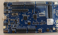
I am trying to test a nRF5340 with a 1.3 inch waveshare 240x240 display using a st7789 driver. How would I connect the display to the board:
|
VCC |
3.3v |
|
GND |
Ground |
|
DIN |
Serial Data |
|
CLK |
Serial Clock |
|
CS |
Chip Select |
|
DC |
Data Command/Control |
|
RST |
Reset |
|
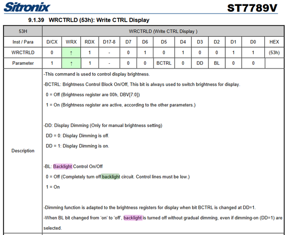
BL |
Backlight |
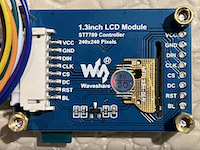
and create an overlay file representing the display connections?