Using two channels of one timer

Hello,

I am trying to use two channels on one timer0, to handle two gpiote tasks to toggle two on-board leds on nRF52840 DK. I am using two ppi channels to handle this.

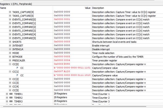
I have set the timer0_ticks0 and timer0_ticks1 as 250ms and 500ms and used extended compare on both the channels to generate a compare events accordingly.

I could see from the EVENTS_COMPARE[n] register, that only EVENTS_COMPARE[0] is triggered and not the other.

Diggging into it a little bit shown that only the lowest value from CC[n] gets a compare event.

Please find the code here. Any clarification on this is highly appreciated.

KInd regards

/** @file
*
* @ppi_timer_leds main.c
* @{
* @ingroup ppi_timer_leds
* @brief PPI TIMER0 CH0 and CH1 Application main file.
*
* This file contains the source code for a sample application using GPIOTE, TIMER; PPI.
*/

#include <stdbool.h>
#include <stdint.h>
#include "nrf.h"
#include "nrf_gpiote.h"
#include "nrf_gpio.h"
#include "boards.h"
#include "nrfx_timer.h"
#include "nrfx_ppi.h"
#include "nrfx_gpiote.h"
#include "nrf_timer.h"
#include "nrf_gpiote.h"
#include "nrf_ppi.h"
#include "nrf_drv_ppi.h"
#include "nrf_drv_timer.h"
#include "nrf_drv_gpiote.h"
#include "app_error.h"


#define LED1    13
#define LED2    14
#define LED3    15
#define LED4    16

#define B1      11
#define B2      12
#define B3      24
#define B4      25


static uint32_t tep_led1;
static uint32_t tep_led2;
static uint32_t eep0_timer0;
static uint32_t eep1_timer0;
static nrf_ppi_channel_t ppi_channel0;  //for timer0_ch0 event and led1 toggle task at 500ms
static nrf_ppi_channel_t ppi_channel1;  //for timer0_ch1 event and led2 toggle task at 1000ms

//Function prototypes
void gpiote_init();
void timer0_init();
void dummy_timer0_evnthndlr();


int main(void)
{
  uint32_t  err_code = NRF_SUCCESS;

  gpiote_init();
  timer0_init();

  //Allocate a PPI channel 0
  err_code =  nrfx_ppi_channel_alloc(&ppi_channel0);
  APP_ERROR_CHECK(err_code);

    //Allocate a PPI channel 1
  err_code =  nrfx_ppi_channel_alloc(&ppi_channel1);
  APP_ERROR_CHECK(err_code);

  //Assign EEPs and TEPs to the PPI channel0
  nrfx_ppi_channel_assign(ppi_channel0, eep0_timer0, tep_led1);

  //Assign EEPs and TEPs to the PPI channel1
  nrfx_ppi_channel_assign(ppi_channel1, eep1_timer0, tep_led2);

  //Enable ppi channel
  err_code = nrfx_ppi_channel_enable(ppi_channel0);
  APP_ERROR_CHECK(err_code);
  err_code = nrfx_ppi_channel_enable(ppi_channel1);
  APP_ERROR_CHECK(err_code);

    while (true)
    {
        // Do Nothing - GPIO can be toggled without software intervention.
    }
}

void gpiote_init()
{
  uint32_t err_code = NRF_SUCCESS;

  //configure gpiote out task
  nrfx_gpiote_out_config_t out_config1 = NRFX_GPIOTE_CONFIG_OUT_TASK_TOGGLE(true); //out task to toggle the pin state
  nrfx_gpiote_out_config_t out_config2 = NRFX_GPIOTE_CONFIG_OUT_TASK_TOGGLE(true); //out task to toggle the pin state

  //Initialize gpiote modlue
  err_code = nrfx_gpiote_init();
  APP_ERROR_CHECK(err_code);
  
  //init gpiote for the desired pin- LED1 pin 13
  err_code = nrfx_gpiote_out_init(LED1, &out_config1);
  APP_ERROR_CHECK(err_code);
    err_code = nrfx_gpiote_out_init(LED2, &out_config2);
  APP_ERROR_CHECK(err_code);

  //Enable gpiote led1 task
  nrfx_gpiote_out_task_enable(LED1);
    //Enable gpiote led2 task
  nrfx_gpiote_out_task_enable(LED2);

  //get the address of the gpiote out toggle task for led1
  tep_led1 = nrfx_gpiote_out_task_addr_get(LED1);
  
  //get the address of the gpiote out toggle task for led2
  tep_led2 = nrfx_gpiote_out_task_addr_get(LED2);
}

void timer0_init()
{
  uint32_t err_code = NRF_SUCCESS;

  //Timer0 is instatiated
  nrfx_timer_t timer0 = NRFX_TIMER_INSTANCE(0);
  
  //Configure timer 0. Look at the macro for parameter details
  nrfx_timer_config_t timer0_cfg = NRFX_TIMER_DEFAULT_CONFIG;
  timer0_cfg.frequency = NRF_TIMER_FREQ_1MHz;
  timer0_cfg.mode = NRF_TIMER_MODE_TIMER;
  timer0_cfg.bit_width = NRF_TIMER_BIT_WIDTH_32;
  timer0_cfg.interrupt_priority = 6;
  
  //from ms to ticks
  uint32_t timer0_ticks0 = nrfx_timer_ms_to_ticks(&timer0, 250);
  uint32_t timer0_ticks1 = nrfx_timer_ms_to_ticks(&timer0, 500);
  
  //Initialize the timer
  err_code = nrfx_timer_init(&timer0, &timer0_cfg, dummy_timer0_evnthndlr);
  APP_ERROR_CHECK(err_code);

  //setting the timer channel in the extended compare mode.
  nrfx_timer_extended_compare(&timer0, NRF_TIMER_CC_CHANNEL0, timer0_ticks0, NRF_TIMER_SHORT_COMPARE0_CLEAR_MASK, false);
  nrfx_timer_extended_compare(&timer0, NRF_TIMER_CC_CHANNEL1, timer0_ticks1, NRF_TIMER_SHORT_COMPARE1_CLEAR_MASK, false);

  //get timer0 event address
  eep0_timer0 = nrfx_timer_event_address_get(&timer0, NRF_TIMER_EVENT_COMPARE0);
  eep1_timer0 = nrfx_timer_event_address_get(&timer0, NRF_TIMER_EVENT_COMPARE1);

  //enable timer0
  nrfx_timer_enable(&timer0);

  
}

void dummy_timer0_evnthndlr()
{
  
}


/** @} */

Parents
  • Hello,

      //setting the timer channel in the extended compare mode.
      nrfx_timer_extended_compare(&timer0, NRF_TIMER_CC_CHANNEL0, timer0_ticks0, NRF_TIMER_SHORT_COMPARE0_CLEAR_MASK, false);
      nrfx_timer_extended_compare(&timer0, NRF_TIMER_CC_CHANNEL1, timer0_ticks1, NRF_TIMER_SHORT_COMPARE1_CLEAR_MASK, false);

    The 'NRF_TIMER_SHORT_COMPARE0_CLEAR_MASK' flag will cause the TIMER counter register to be cleared after you get the COMPARE0 event, see register description for the TIMER.SHORTS register. As a result, the counter will never reach COMPARE1 value. 

    Best regards,

    Vidar

  • Hi Vidar,

    thanks for your reply. As you might have seen from my use case that I am trying to use one timer to invoke two compare events. I also have the need to use ppi. 

    Reason for me to use one timer: I have a need to use one pin on the SoC to measure pwm: (pulse width and period). My understanding is that I could use one timer with two channels to achieve this, of course with ppi. 
    If this can't be realized, do you have any recommendation to this use case?

    Thank you.
    Kind regards

  • Hi,

    Is the COMPARE0 period always going to be equal to half the COMPARE1 period? If so, you can use the PPI fork feature to have the COMPARE1 event also trigger the first endpoint.

    Example:

    /** @file
    *
    * @ppi_timer_leds main.c
    * @{
    * @ingroup ppi_timer_leds
    * @brief PPI TIMER0 CH0 and CH1 Application main file.
    *
    * This file contains the source code for a sample application using GPIOTE, TIMER; PPI.
    */
    
    #include <stdbool.h>
    #include <stdint.h>
    #include "nrf.h"
    #include "nrf_gpiote.h"
    #include "nrf_gpio.h"
    #include "boards.h"
    #include "nrfx_timer.h"
    #include "nrfx_ppi.h"
    #include "nrfx_gpiote.h"
    #include "nrf_timer.h"
    #include "nrf_gpiote.h"
    #include "nrf_ppi.h"
    #include "nrf_drv_ppi.h"
    #include "nrf_drv_timer.h"
    #include "nrf_drv_gpiote.h"
    #include "app_error.h"
    
    
    #define LED1    13
    #define LED2    14
    #define LED3    15
    #define LED4    16
    
    #define B1      11
    #define B2      12
    #define B3      24
    #define B4      25


    static uint32_t tep_led1;
    static uint32_t tep_led2;
    static uint32_t eep0_timer0;
    static uint32_t eep1_timer0;
    static nrf_ppi_channel_t ppi_channel0;  //for timer0_ch0 event and led1 toggle task at 500ms
    static nrf_ppi_channel_t ppi_channel1;  //for timer0_ch1 event and led2 toggle task at 1000ms
    
    //Function prototypes
    void gpiote_init();
    void timer0_init();
    void dummy_timer0_evnthndlr(nrf_timer_event_t event_type,
                                void            * p_context);
    
    
    int main(void)
    {
      uint32_t  err_code = NRF_SUCCESS;
    
      //Start HFXO for increased accuracy
      NRF_CLOCK->EVENTS_HFCLKSTARTED = 0;
      NRF_CLOCK->TASKS_HFCLKSTART = 1;
      while (NRF_CLOCK->EVENTS_HFCLKSTARTED == 0);
    
      gpiote_init();
      timer0_init();
    
      //Allocate a PPI channel 0
      err_code =  nrfx_ppi_channel_alloc(&ppi_channel0);
      APP_ERROR_CHECK(err_code);
    
        //Allocate a PPI channel 1
      err_code =  nrfx_ppi_channel_alloc(&ppi_channel1);
      APP_ERROR_CHECK(err_code);
    
      //Assign EEPs and TEPs to the PPI channel0
      nrfx_ppi_channel_assign(ppi_channel0, eep0_timer0, tep_led1);
    
      //Assign EEPs and TEPs to the PPI channel1
      nrfx_ppi_channel_assign(ppi_channel1, eep1_timer0, tep_led2);
      
      // fork eep1_timer0 EEP to tep_led1 endpoint
      nrfx_ppi_channel_fork_assign(ppi_channel1, tep_led1);
    
      //Enable ppi channel
      err_code = nrfx_ppi_channel_enable(ppi_channel0);
      APP_ERROR_CHECK(err_code);
      err_code = nrfx_ppi_channel_enable(ppi_channel1);
      APP_ERROR_CHECK(err_code);
    
        while (true)
        {
            // Do Nothing - GPIO can be toggled without software intervention.
        }
    }
    
    void gpiote_init()
    {
      uint32_t err_code = NRF_SUCCESS;
    
      //configure gpiote out task
      nrfx_gpiote_out_config_t out_config1 = NRFX_GPIOTE_CONFIG_OUT_TASK_TOGGLE(true); //out task to toggle the pin state
      nrfx_gpiote_out_config_t out_config2 = NRFX_GPIOTE_CONFIG_OUT_TASK_TOGGLE(true); //out task to toggle the pin state
    
      //Initialize gpiote modlue
      err_code = nrfx_gpiote_init();
      APP_ERROR_CHECK(err_code);
      
      //init gpiote for the desired pin- LED1 pin 13
      err_code = nrfx_gpiote_out_init(LED1, &out_config1);
      APP_ERROR_CHECK(err_code);
        err_code = nrfx_gpiote_out_init(LED2, &out_config2);
      APP_ERROR_CHECK(err_code);
    
      //Enable gpiote led1 task
      nrfx_gpiote_out_task_enable(LED1);
        //Enable gpiote led2 task
      nrfx_gpiote_out_task_enable(LED2);
    
      //get the address of the gpiote out toggle task for led1
      tep_led1 = nrfx_gpiote_out_task_addr_get(LED1);
      
      //get the address of the gpiote out toggle task for led2
      tep_led2 = nrfx_gpiote_out_task_addr_get(LED2);
    }
    
    void timer0_init()
    {
      uint32_t err_code = NRF_SUCCESS;
    
      //Timer0 is instatiated
      nrfx_timer_t timer0 = NRFX_TIMER_INSTANCE(0);
      
      //Configure timer 0. Look at the macro for parameter details
      nrfx_timer_config_t timer0_cfg = NRFX_TIMER_DEFAULT_CONFIG;
      timer0_cfg.frequency = NRF_TIMER_FREQ_1MHz;
      timer0_cfg.mode = NRF_TIMER_MODE_TIMER;
      timer0_cfg.bit_width = NRF_TIMER_BIT_WIDTH_32;
      timer0_cfg.interrupt_priority = 6;
      
      //from ms to ticks
      uint32_t timer0_ticks0 = nrfx_timer_ms_to_ticks(&timer0, 250);
      uint32_t timer0_ticks1 = nrfx_timer_ms_to_ticks(&timer0, 500);
      
      //Initialize the timer
      err_code = nrfx_timer_init(&timer0, &timer0_cfg, dummy_timer0_evnthndlr);
      APP_ERROR_CHECK(err_code);
    
      //setting the timer channel in the extended compare mode.
      //nrfx_timer_extended_compare(&timer0, NRF_TIMER_CC_CHANNEL0, timer0_ticks0, NRF_TIMER_SHORT_COMPARE0_CLEAR_MASK, false);
      nrfx_timer_compare(&timer0, NRF_TIMER_CC_CHANNEL0, timer0_ticks0, false);
      nrfx_timer_extended_compare(&timer0, NRF_TIMER_CC_CHANNEL1, timer0_ticks1, NRF_TIMER_SHORT_COMPARE1_CLEAR_MASK, false);
    
      //get timer0 event address
      eep0_timer0 = nrfx_timer_event_address_get(&timer0, NRF_TIMER_EVENT_COMPARE0);
      eep1_timer0 = nrfx_timer_event_address_get(&timer0, NRF_TIMER_EVENT_COMPARE1);
    
      //enable timer0
      nrfx_timer_enable(&timer0);
    
      
    }
    
    void dummy_timer0_evnthndlr(nrf_timer_event_t event_type,
                                void            * p_context)
    {
      
    }
    
    
    /** @} */

    Kind regards,

    Vidar

  • Hi Vidar,

    thanks for your reply. II have selected those Periods just as PoC to understand if different channels from a timer could be used to get event triggers.

    It was quite informtive to see that task2 could be forked to be trigegred when the task1 is triggered by the event1 with ppi. Perhaps I can think of utilizing this feature. 

    Perhaps for now we can close this ticket. I will do my pwm measure implementation and will create a new ticket if I have any bottlenecks.

    Thanks for your support.

    Kind regards

  • Hi,

    Unfortunately, I have not attempted to sample a PWM signal using timers and GPIOTE before, nor am I aware of any example codes that demonstrate this. However, feel free to keep this ticket open or create a new one in case you encounter any problems when you try to implement it. 

    Kind regards,

    Vidar

Reply Children
No Data
Related