
Im trying to measure the time between 2 consecutive rising endges (Rising and Falling Edge together) on GPIO continuously but I did not find any leads. will appreciate the support.
Im trying to measure the time between 2 consecutive rising endges (Rising and Falling Edge together) on GPIO continuously but I did not find any leads. will appreciate the support.
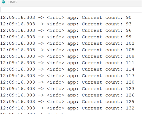 after implementing the ppi example I start getting these values. But these values are in ms. How can I increase to nano seconds only the output so that i can capture upto 900 nano seconds

#include <stdint.h>

#include "nrf_delay.h"
#include "app_error.h"

#include "nrf_drv_ppi.h"
#include "nrf_drv_timer.h"

#include "nrf_log.h"
#include "nrf_log_ctrl.h"
#include "nrf_log_default_backends.h"
//nrf_drv_timer_us_to_ticks
#define PPI_EXAMPLE_TIMERS_us_PHASE_SHIFT_DELAY    (1)    // 1s = 10 * 100ms (Timer 0 interrupt)
#define PPI_EXAMPLE_TIMER0_us_INTERVAL             (1)   // Timer interval in milliseconds
#define PPI_EXAMPLE_TIMER1_us_INTERVAL             (1)  // Timer interval in milliseconds
#define PPI_EXAMPLE_TIMER2_us_INTERVAL             (1)  // Timer interval in milliseconds


static const nrf_drv_timer_t m_timer0 = NRF_DRV_TIMER_INSTANCE(0);
static const nrf_drv_timer_t m_timer1 = NRF_DRV_TIMER_INSTANCE(1);
static const nrf_drv_timer_t m_timer2 = NRF_DRV_TIMER_INSTANCE(2);

static nrf_ppi_channel_t m_ppi_channel1;
static nrf_ppi_channel_t m_ppi_channel2;

static volatile uint32_t m_counter;

static void timer0_event_handler(nrf_timer_event_t event_type, void * p_context)
{
    ++m_counter;
}

/* Timer event handler. Not used since Timer1 and Timer2 are used only for PPI. */
static void empty_timer_handler(nrf_timer_event_t event_type, void * p_context)
{
}


/** @brief Function for initializing the PPI peripheral.
*/
static void ppi_init(void)
{
    uint32_t err_code = NRF_SUCCESS;

    err_code = nrf_drv_ppi_init();
    APP_ERROR_CHECK(err_code);

    /* Configure 1st available PPI channel to stop TIMER0 counter on TIMER1 COMPARE[0] match,
     * which is every even number of seconds.
     */
    err_code = nrf_drv_ppi_channel_alloc(&m_ppi_channel1);
    APP_ERROR_CHECK(err_code);
    err_code = nrf_drv_ppi_channel_assign(m_ppi_channel1,
                                          nrf_drv_timer_event_address_get(&m_timer1,
                                                                          NRF_TIMER_EVENT_COMPARE0),
                                          nrf_drv_timer_task_address_get(&m_timer0,
                                                                         NRF_TIMER_TASK_STOP));
    APP_ERROR_CHECK(err_code);

    /* Configure 2nd available PPI channel to start TIMER0 counter at TIMER2 COMPARE[0] match,
     * which is every odd number of seconds.
     */
    err_code = nrf_drv_ppi_channel_alloc(&m_ppi_channel2);
    APP_ERROR_CHECK(err_code);
    err_code = nrf_drv_ppi_channel_assign(m_ppi_channel2,
                                          nrf_drv_timer_event_address_get(&m_timer2,
                                                                          NRF_TIMER_EVENT_COMPARE0),
                                          nrf_drv_timer_task_address_get(&m_timer0,
                                                                         NRF_TIMER_TASK_START));
    APP_ERROR_CHECK(err_code);

    // Enable both configured PPI channels
    err_code = nrf_drv_ppi_channel_enable(m_ppi_channel1);
    APP_ERROR_CHECK(err_code);
    err_code = nrf_drv_ppi_channel_enable(m_ppi_channel2);
    APP_ERROR_CHECK(err_code);
}


/** @brief Function for Timer 0 initialization.
 *  @details Timer 0 will be stopped and started by Timer 1 and Timer 2 respectively using PPI.
 *           It is configured to generate an interrupt every 100ms.
 */
static void timer0_init(void)
{
    // Check TIMER0 configuration for details.
    nrf_drv_timer_config_t timer_cfg = NRF_DRV_TIMER_DEFAULT_CONFIG;
    timer_cfg.frequency = NRF_TIMER_FREQ_16MHz;
    ret_code_t err_code = nrf_drv_timer_init(&m_timer0, &timer_cfg, timer0_event_handler);
    APP_ERROR_CHECK(err_code);

    nrf_drv_timer_extended_compare(&m_timer0,
                                   NRF_TIMER_CC_CHANNEL0,
                                   nrf_drv_timer_ms_to_ticks(&m_timer0,
                                                             PPI_EXAMPLE_TIMER0_us_INTERVAL),
                                   NRF_TIMER_SHORT_COMPARE0_CLEAR_MASK,
                                   true);
}

/** @brief Function for Timer 1 initialization.
 *  @details Initializes TIMER1 peripheral to generate an event every 2 seconds. The events are
 *           generated at even numbers of seconds after starting the example (2, 4, 6 ...) and they
 *           are used to stop TIMER0 via PPI: TIMER1->EVENT_COMPARE[0] triggers TIMER0->TASK_STOP.
 */
static void timer1_init(void)
{
    // Check TIMER1 configuration for details.
    nrf_drv_timer_config_t timer_cfg = NRF_DRV_TIMER_DEFAULT_CONFIG;
    timer_cfg.frequency = NRF_TIMER_FREQ_16MHz;
    ret_code_t err_code = nrf_drv_timer_init(&m_timer1, &timer_cfg, empty_timer_handler);
    APP_ERROR_CHECK(err_code);

    nrf_drv_timer_extended_compare(&m_timer1,
                                   NRF_TIMER_CC_CHANNEL0,
                                   nrf_drv_timer_ms_to_ticks(&m_timer1,
                                                             PPI_EXAMPLE_TIMER1_us_INTERVAL),
                                   NRF_TIMER_SHORT_COMPARE0_CLEAR_MASK,
                                   false);
}


/** @brief Function for Timer 2 initialization.
 *  @details Initializes TIMER2 peripheral to generate an event every 2 seconds. The events are
 *           generated at odd numbers of seconds after starting the example (3, 5, 7 ...) and they
 *           are used to start TIMER0 via PPI: TIMER2->EVENT_COMPARE[0] triggers TIMER0->TASK_START.
 */
static void timer2_init(void)
{
    // Check TIMER2 configuration for details.
    nrf_drv_timer_config_t timer_cfg = NRF_DRV_TIMER_DEFAULT_CONFIG;
    timer_cfg.frequency = NRF_TIMER_FREQ_16MHz;
    ret_code_t err_code = nrf_drv_timer_init(&m_timer2, &timer_cfg, empty_timer_handler);
    APP_ERROR_CHECK(err_code);

    nrf_drv_timer_extended_compare(&m_timer2,
                                   NRF_TIMER_CC_CHANNEL0,
                                   nrf_drv_timer_ms_to_ticks(&m_timer2,
                                                             PPI_EXAMPLE_TIMER2_us_INTERVAL),
                                   NRF_TIMER_SHORT_COMPARE0_CLEAR_MASK,
                                   false);
}

/**
 * @brief Function for application main entry.
 */
int main(void)
{
    uint32_t old_val = 0;
    uint32_t err_code;

    err_code = NRF_LOG_INIT(NULL);
    APP_ERROR_CHECK(err_code);

    NRF_LOG_DEFAULT_BACKENDS_INIT();

    ppi_init();
    timer0_init(); // Timer used to increase m_counter every 100ms.
    timer1_init(); // Timer to generate events on even number of seconds - stopping Timer 0
    timer2_init(); // Timer to generate events on odd number of seconds - starting Timer 0

    NRF_LOG_INFO("PPI example started.");

    // Start clock.
    nrf_drv_timer_enable(&m_timer0);

    /* Below delay is implemented to ensure that Timer0 interrupt will execute before PPI action.
     * Please be aware that such solution was tested only in this simple example code. In case
     * of more complex systems with higher level interrupts this may lead to not correct timers
     * synchronization.
     */
    nrf_delay_us(1);
    nrf_drv_timer_enable(&m_timer1);

    m_counter = (uint32_t)-PPI_EXAMPLE_TIMERS_us_PHASE_SHIFT_DELAY;

    // Timer 2 will start one second after Timer 1 (m_counter will equal 0 after 1s)
 //   while (m_counter != 0)
   // {
        // just wait
    //}
    nrf_drv_timer_enable(&m_timer2);

    while (true)
    {
        uint32_t counter = m_counter;
        if (old_val != counter)
        {
            old_val = counter;

            NRF_LOG_INFO("Current count: %u", counter);
            NRF_LOG_FLUSH();
        }
    }
}

/** @} */
I changed the frequency from 31250Hz to 16MHz, but resolution did not get affected. The one more thing I did not uses LFCLK (crystal) as this was the optional for custom board.
Hi Vidar, Thanks for your reply and appreciate.
I tried this code but not able to see any results on the com port.
can you please help me to het it work.

Hi,
Did you verify that you are feeding the input signal into the correct pin (SIG_INPUT_PIN)? You can also connect SIG_INPUT_PIN to SIG_OUT_PIN externally to measure the frequency of the generated output signal.
I want to make an addition that I will measure 3 inputs on gpios. I was trying to test for 1, so that I will follow the same steps to implement for 3, but still trying to make it work for single. Thanks
I recommend you start with one input first to see if you can get it to work. You will not be able to sample a high-frequency input continuously or multiple inputs simultaneously anyway.
yes im trying to make it work for 1 input on 1 gpio.
is it confirmed that I can't get a 3 frequencies on 3 different GPIO'S ???
yes im trying to make it work for 1 input on 1 gpio.
is it confirmed that I can't get a 3 frequencies on 3 different GPIO'S ???