I2S first and second cycle data is not available, causing a problem with the level.

Hi,

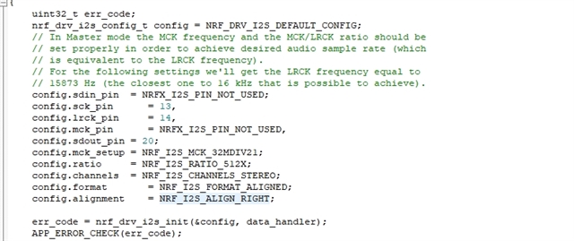
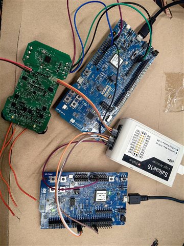
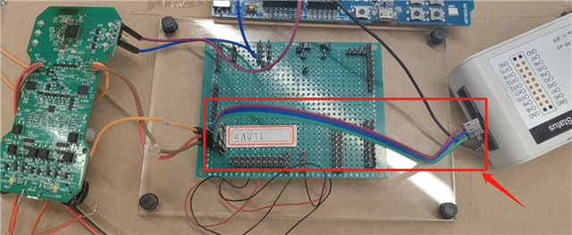
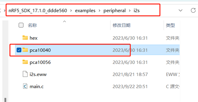
I used the example in SDK_17.1 and NRF52DK board to test I2S.

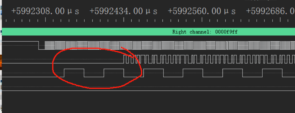
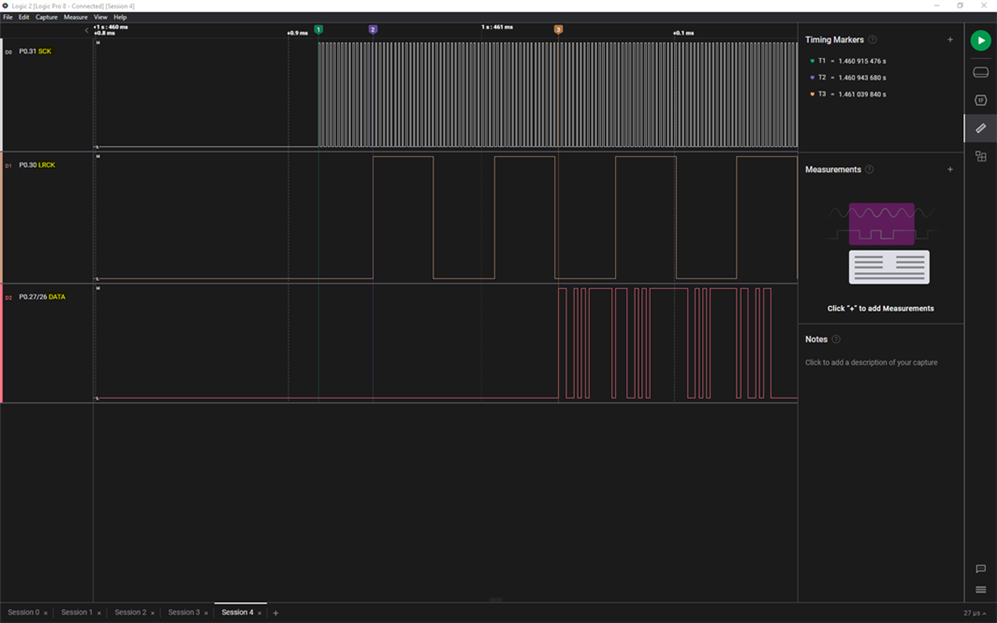
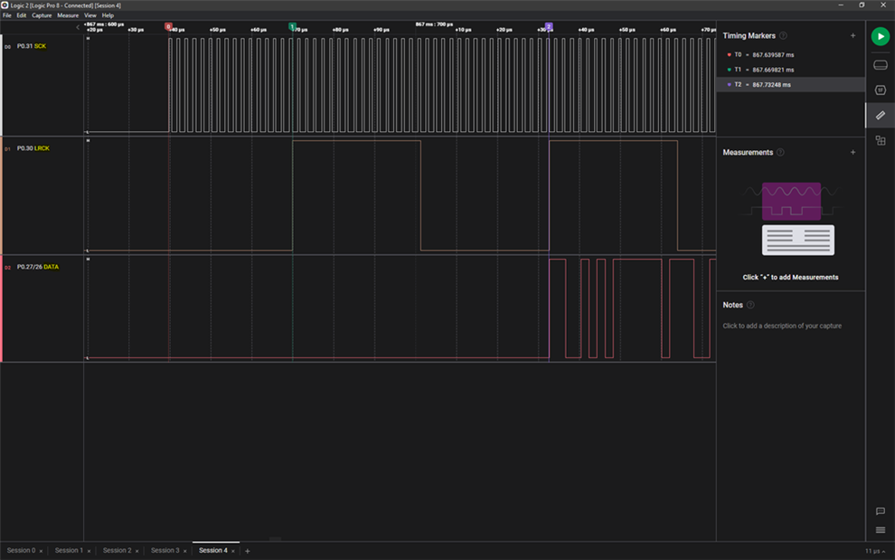
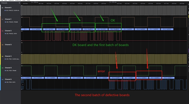
The logical analysis instrument picked up the following waveform:

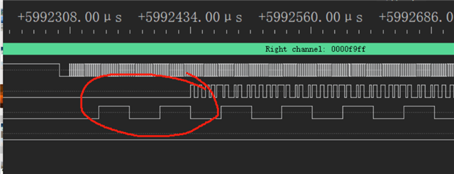
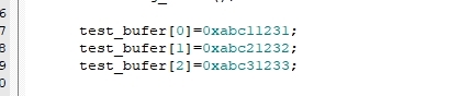
As you can see, the data was initially absent, causing a problem with the data input pin level on the I2S hardware I plugged in. What I want to know is how I should configure the data to be transferred from the very beginning.

Best regards,

Stars

  • HI,

    What changes have you made to the example? 

    What bit rate are you using?

    We have info on use and configuration information here https://infocenter.nordicsemi.com/topic/com.nordic.infocenter.nrf52832.ps.v1.1/i2s.html?cp=5_2_0_43#concept_z2v_24y_vr . 

    Regards,
    Jonathan

  • Hi,

    I used the default example and didn't make any changes. The requirement is that you want the data to be synchronized with the clock. Can you reproduce the phenomenon using nrf52DK?

    For example, there is no data in the red circled part of the picture. I want the data to appear with the clock. Is that even possible? Or my understanding of I2S is wrong, I2S communication, the first part of the data and the clock is not synchronized?

    Best regards,

    Stars

  • Hi Stars,

    Yes I can preproduce this on the 52DK. I have done some testing, and fond that there will always be some gap in time from when the clock's start and to when the data is sent. But it also depends on the format mode used. 

    In the default mode, also known as I2S mode, each frame contains one left and right sample pair, with the left sample being transferred during the low half period of LRCK followed by the right sample being transferred during the high period of LRCK 1.

    In Aligned mode, each frame contains one left and right sample pair, with the left sample being transferred during the high half period of LRCK followed by the right sample being transferred during the low period of LRCK 1. Consequently, the LRCK frequency is equivalent to the audio sample rate


    It never start on the first rising\falling edge of the LRCK, but from the second shift it is either after the rising or falling.  


    Regards,
    Jonathan

  • Hi Jonathan,

    Now we can accept empty data for the first few cycles at startup, but a new fatal problem has been discovered.

    We have two batches of boards, and the equipment of the first batch is consistent with the DK board. However, the second batch of boards had equipment problems: the transmission of left and right channel data, the right channel data to cover the left channel data.

    The comparison test is as follows:

    1.The chip is completely erased before each download

    2.The program configuration is the same, right-justified:

    Test data are as follows:

    3.Download the program to the DK board and the second batch of faulty equipment, and collect the waveform:

    Why does this happen? And confirmed that the silk screen on the two batches of chips are N52832-QFAAG1-2238AT.

    This problem has a great impact on our development process, please provide me with some ideas to determine the cause of the problem.

    Best regards,

    Stars

  • Hi,

    After testing, the correct data can be obtained if a wire is added directly to the logic analyzer and the three output pins of the I2S.

    We suspect a parasitic capacitor on the wire is making the data normal, but why is that?

    Can you give me some advice on screening?

    Best regards,

    Stars

Related