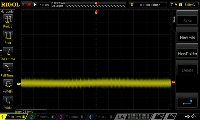
We want to read the GPIO voltage level. Per the documentation this should be possible by using input 9 and the internal reference. What I am observing is that probing the pin with a multimeter reads 1.78 V. The ADC is giving me 1.68 - 1.72V. I've tweaked several of the configurations and this is the best I am getting.
Is there any special considerations for reading the GPI voltage this way?
Implementation below:
// CODE TO READ THE VDD_GPIO
// With internal reference, single ended input (grounded negative input), and a gain of 1/6 the input range
// will be:
// Input range = (0.6 V)/(1/6) = 3.6 V

#include <device.h>
#include <drivers/gpio.h>
#include <drivers/adc.h>
#include <hal/nrf_saadc.h>

#define ADC_DEVICE_NODE DT_INST(0, nordic_nrf_saadc)
#define VRAIL_ADC_GAIN ADC_GAIN_1_4
#define ADC_REFERENCE ADC_REF_INTERNAL
#define ADC_ACQUISITION_TIME ADC_ACQ_TIME(ADC_ACQ_TIME_MICROSECONDS, 40)
#define ADC_CHANNEL_INPUT NRF_SAADC_INPUT_VDD
#define ADC_CHAN_ID 0
#define ADC_RESOLUTION (14)
#define NUMBER_OF_EXTRA_SAMPLES (1)

static bool adc_calibrate_do = true;

struct device* adc_dev;
struct adc_channel_cfg adc_channel_config =
{
	.gain = VRAIL_ADC_GAIN,
	.reference = ADC_REFERENCE,
	.acquisition_time = ADC_ACQUISITION_TIME,
	.channel_id = ADC_CHAN_ID,
	.differential = false,
	.input_positive = ADC_CHANNEL_INPUT,
};

const struct adc_sequence_options sequence_opts =
{
		.interval_us = 10,
		.callback = NULL,
		.user_data = NULL,
		.extra_samplings = NUMBER_OF_EXTRA_SAMPLES,
};

bool util_set_up_rail_adc(void)
{
	bool ret = true;

	adc_dev = DEVICE_DT_GET(ADC_DEVICE_NODE);

	if (!adc_dev) {
		LOG_ERR("device_get_binding ADC_0 failed\n");
		ret = false;
	}
	int err = adc_channel_setup(adc_dev, &adc_channel_config);
	if (err) {
		LOG_ERR("Error in adc setup: %d\n", err);
		ret = false;
	}

	return ret;
}

int util_get_rail_millivolts(int* adc_read_val)
{
	int ret = -ENOENT;
	int16_t raw_sample_buffer[NUMBER_OF_EXTRA_SAMPLES + 1];
	const struct adc_sequence sequence = {
		.options = &sequence_opts,
		.channels = BIT(ADC_CHAN_ID),
		.buffer = raw_sample_buffer,
		.buffer_size = sizeof(raw_sample_buffer),
		.resolution = ADC_RESOLUTION,
		.oversampling = 4,
		.calibrate = adc_calibrate_do,
	};

	if (!adc_dev) {
		return ret;
	}

	ret = adc_read(adc_dev, &sequence);

	// Set to false so subsequence calls to util_get_rail_millivolts do not
	// trigger calibration.
	adc_calibrate_do = false;

	// Do a rolling average of all samples.
	int avg_mv_reading = -1;
	for (int x = 0; x < (NUMBER_OF_EXTRA_SAMPLES + 1); x++)
	{
		int adc_mv = raw_sample_buffer[x];
		ret = adc_raw_to_millivolts(adc_ref_internal(adc_dev), adc_channel_config.gain, sequence.resolution, &adc_mv);
		if (ret >= 0)
		{
			LOG_DBG("RAIL RAW %d ~ %d mV", raw_sample_buffer[x], adc_mv);
			if (x == 0)
			{
				avg_mv_reading = adc_mv;
			}
			else
			{
				avg_mv_reading = (avg_mv_reading + adc_mv)/2;
			}

		}
	}

	if (ret >= 0)
	{
		*adc_read_val = avg_mv_reading;
		LOG_INF("RAIL AVG %d mV", avg_mv_reading);
	}

	return ret;
}


