UART Communication Issue between ESP32 and NRF9160 using at_client

Hello,

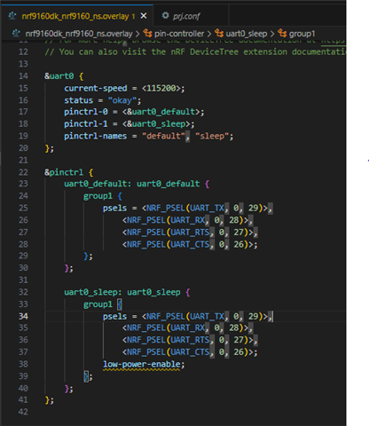
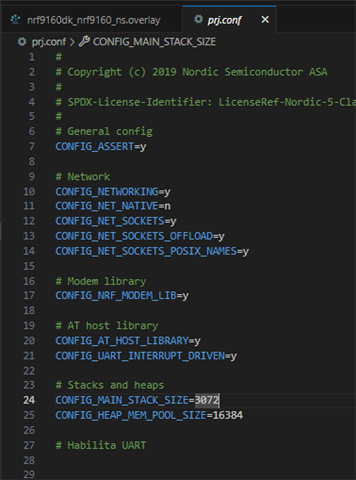
I am working on a project where I need to establish UART communication between an ESP32 and an NRF9160. I used the at_client example provided in the Nordic SDK to set up the communication. I have managed to send commands from the ESP32 to the NRF9160 successfully, and these commands are acknowledged and executed correctly by the NRF9160. However, I am facing an issue where the NRF9160 does not send any response or data back to the ESP32, instead, the responses are sent to the PC terminal.

I appreciate any help or suggestions to resolve this issue.

Thank you.

  • Hi Carlos

    Can you show me the code you are using to send the response from the nRF9160? 

    Is the PC terminal using UART as well, or is it using the Segger RTT driver? 

    Sounds like possibly the response is being sent to the wrong UART interface, if you are using one for the terminal and one for the AT commands. 

    Best regards
    Torbjørn

  • Hi Torbjørn,

    Thank you for your message. In response to your inquiry, the PC terminal is utilizing UART for communication via the micro USB port integrated on the nRF9160 board.

    Attached, you will find two files:

    1. The file at_client.c, which contains the code I am using on the nRF9160 to send responses.
    2. The file main.py, which contains the MicroPython code I am using on the ESP32 for communication.

    I hope this clarifies how I am handling communication between these devices. If there’s anything more I can assist with or if you need further information, feel free to let me know.

    Best regards,

    Carlos Romero

    4405.at_client.rarESP32.rar

  • Hi Carlos

    It seems to me you only have one UART interface enabled, is this intentional? 

    The only UART I can find referenced in your code is uart0, and even though you have an overlay the pins seem to be the same as default. This means that this UART will be connected to the UART interface on the DK board controller chip, and as such it will be available on the terminal on the PC side. 

    If you are also connecting your ESP device to the same lines it means you essentially have 3 devices connected to the same UART pins, which will cause issues certainly. 

    I would recommend using uart1 for the communication with the ESP chip instead, and keep uart0 for logging purposes. Then you can still use the normal logging functionalities, while dedicating uart1 for the ESP communication only. 

    By default the nRF9160DK board files will dedicated uart1 for the arduino serial and enable it, assigned to the pins listed below, but you can move this uart interface to different pins if you want:

    	uart1_default: uart1_default {
    		group1 {
    			psels = <NRF_PSEL(UART_TX, 0, 1)>,
    				<NRF_PSEL(UART_RTS, 0, 14)>;
    		};
    		group2 {
    			psels = <NRF_PSEL(UART_RX, 0, 0)>,
    				<NRF_PSEL(UART_CTS, 0, 15)>;
    			bias-pull-up;
    		};
    	};

    Best regards
    Torbjørn

  • Hello Torbjørn,

    Thank you for your response and recommendations. I have tried configuring UART1 for communication with the ESP chip and maintaining UART0 for other matters. However, I am experiencing some problems with the AT commands; it does not communicate correctly unless it is with uart0 and the extender pins.

    I made the following configurations in the nrf9160dk_nrf9160_ns.overlay file to set the UART1 pins and to set it as default in the at-host, but still, when I send AT commands, I only receive empty strings in response.

    &pinctrl {
        uart0_default: uart0_default {
            group1 {
                psels = <NRF_PSEL(UART_TX, 0, 29)>,
                        <NRF_PSEL(UART_RX, 0, 28)>,
                        <NRF_PSEL(UART_RTS, 0, 27)>,
                        <NRF_PSEL(UART_CTS, 0, 26)>;
            };
        };

        uart0_sleep: uart0_sleep {
            group1 {
                psels = <NRF_PSEL(UART_TX, 0, 29)>,
                        <NRF_PSEL(UART_RX, 0, 28)>,
                        <NRF_PSEL(UART_RTS, 0, 27)>,
                        <NRF_PSEL(UART_CTS, 0, 26)>;
                low-power-enable;
            };
        };

        uart1_default: uart1_default {
            group1 {
                psels = <NRF_PSEL(UART_TX, 0, 1)>,
                        <NRF_PSEL(UART_RX, 0, 0)>,
                        <NRF_PSEL(UART_RTS, 0, 14)>,
                        <NRF_PSEL(UART_CTS, 0, 15)>;
            };
        };

        uart1_sleep: uart1_sleep {
            group1 {
                psels = <NRF_PSEL(UART_TX, 0, 1)>,
                        <NRF_PSEL(UART_RX, 0, 0)>,
                        <NRF_PSEL(UART_RTS, 0, 14)>,
                        <NRF_PSEL(UART_CTS, 0, 15)>;
                low-power-enable;
            };
        };
    };

    / {
        chosen {
            ncs,at-host-uart = &uart1;
        };
    };

    Is there something obvious that I might be overlooking? Or is there something else I should check or configure to make UART1 work for AT communication?

    Any additional help would be greatly appreciated.

    Warm regards, Carlos

  • Hi Carlos,

    I suggest you use a more powerful nRF9160: Serial LTE modem — nRF Connect SDK 2.4.2 documentation (nordicsemi.com) instead of the AT client sample. As its name, it is designed as a serial LTE modem and should just work and you will be able to see the response from UART TX P0.10 of nRF9160DK. A logic analyzer or USB-TTL converter can be used to verify if it is functional on your board.

    There is another sample nRF9160: SLM Shell — nRF Connect SDK 2.4.2 documentation (nordicsemi.com) shows how to implement the host side at commands interpreter.

    Best regards,

    Charlie

Related