nPM1100-EK red LED lighting and a sealed battery

Hi All.
I am testing a 4.2v Li-Ion battery charger mock-up with a Wireless Power Transfer having an nPM1100-EK at the end of the Secondary Stage and using its VOUTB 3v buck output to charge the application circuit. Everything works as expected except for one detail.
If I don't use the device for a long time, let's say one month, and even with no load in the VOUTB output, VBAT goes too low, and when I switch back the system, your nPM1100-EK turns on the red LED, apparently preventing the recharge.
The only way to come around the problem I've found was to remove the battery from the mock-up and charge it directly with an external CC/CV wired power supply till I reach VBAT above 3 volts. Then, if I place the battery back on the wireless charging device, the green LED goes on, seamlessly completing the charging cycle as many times as I need.
The bad news is that the final product will have the battery permanently sealed, so you can't physically reach it, and even if you could, the outcome would not be commercially viable.
Any suggestion?
Thanks

  • Hello,

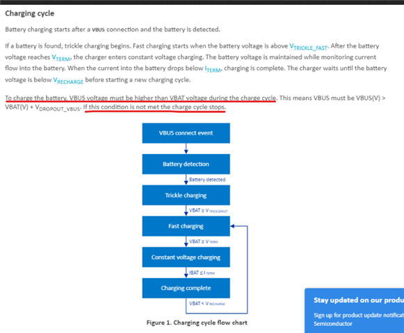
    Can you please check the VBUS voltage? If the VBUS voltage goes below VBAT, battery can not be charged.

    Thanks.

    BR

    Kazi

  • Hi Kazi.

    Of course, in my circuit, the Vbus>Vbat condition is always met since an LDO precedes your nPM1100 with a 5 volts regulated output, whose input is constantly monitored to be between 4,5 and 45 volts.

    In my opinion, the problem arises when Vbat, due to natural auto-discharge, goes below Vbat <2.30V (which, according to your nPM1100-EK User Guide, is the minimum battery operating input range). Then, apparently, and being the battery in perfect condition, you can`t recharge it anymore using an nPM1100 EK PMIC. The ERR LED goes ON and prevents the battery from charging.
    Thanks for your suggestions.
    Best regards.

    Juan

  • Hello Juan,

    You are welcome. 

    You are sure that both voltage of VBUS and VBAT did not go below the minimum range?

    Brown Out Reset (BOR) occurs if both supply voltages /VBAT and VBUS)are below the minimum of the parameter range. The device is held in reset, or System OFF, when both supply voltages VBAT and VBUS are below minimum thresholds.

    The battery monitoring circuit allows the battery voltage to be sampled by the nRF5x ADC. The transistors enable battery voltage sensing through a resistive divider. When not sampling, the transistors prevent current leakage to ground. The circuit is designed to ensure the voltage range on an analog input pin over the battery voltage is within the limits required by the nRF5x GPIO and ADC. A battery voltage of 2.8 V to 4.2 V is scaled down to 360 mV to 540 mV at P0.xx for sampling. If software on nRF5x determines that the battery on nPM1100 is low, the Low Bat LED can be switched on via GPIO. This circuit sources the LED current from VSYS. VSYS will not be supplied after VBAT drops below VBATBOR because CHARGER will isolate the battery when a brownout reset occurs. 

  • Hello Kazi.


    You can be sure that VBUS input voltage is within the recommended operating conditions, that is, between 4,1v and 6,7v.
    The problem occurs when VBAT is below more or less 1,8v (by natural discharge). Then, if I try to recharge the battery by feeding VBUS with 5v (monitored and OK) from the Wireless Power Supply and using the VOUTB 1,8v output, the red LED goes on, and the operation gets cancelled.
    The funny thing is that if I charge the same battery with a conventional wired Power Supply (5v. CC/CV), the problem does not happen.
    (I've tried two nPM1100-EK boards with identical results).
    Any other suggestions?
    Thanks.


    Best regards,

    Juan

    (By the way. VOUTB, despite the red LED affair, was working in both cases. Feeding with the wireless power supply and through the USB connector)

  • Hi Kazi.

    Here I am, still waiting for your comments. Thanks.

    Juan

Related