Hello,
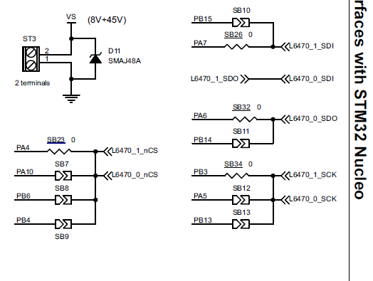
I have experience with Nordic devices but I am new to using Zephyr and nRF Connect SDK. I am trying to use the ST stepper driver chip L6470 with the nRF52832 and Zephyr. I did find the following code on github which appears to be for the ST L6470 for Zephyr.
https://github.com/yashi/st-l6470
When I run the code, I am just trying to get the status from the L6470 driver.
    int status_response = l64x0_get_status(dev);
	printk("L6470 status 0x%0xX\n", status_response);
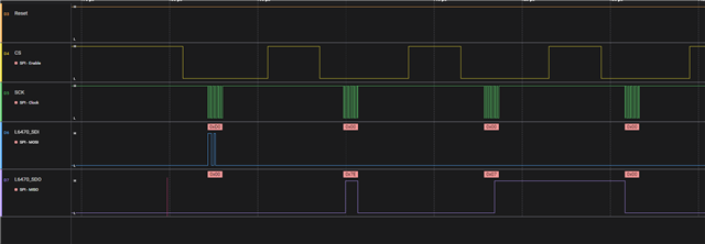
If a status messages is sent to the L6470, the device should send a response back of 0x7E07. On a different design, I have a STM32F4 communicating with a L6470, When the STM32F4 issues the status request, the L6470 responds with 0x7E07.
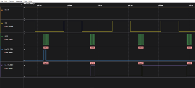
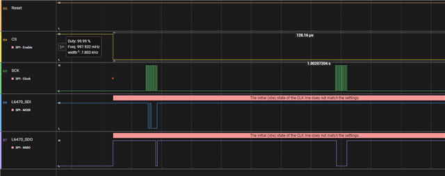
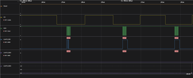
When I am using the code on the nRF52832 trying to get the status from the L6470, I don't see anything on the SDO back from the device when the device sending in the clock pulses.
I am hoping anyone might have some suggestions.
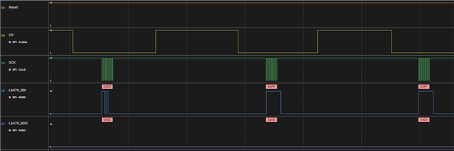
I did modify the code somewhat so I could use some other SPI code that I found. With code, I did see some form of communication back on the SDO line but it was incorrect. So I believe I have the board hooked up correct but I am not sure what I have wrong.
Attached is the modified code. You can use the #define of L6470_CODE to try the one way or the #MY_CODE for the other.
/*
 * Copyright (c) 2016 Intel Corporation
 *
 * SPDX-License-Identifier: Apache-2.0
 */

#include <zephyr/logging/log.h>
LOG_MODULE_REGISTER(app, LOG_LEVEL_DBG);

#include <zephyr/kernel.h>
#include <zephyr/device.h>
#include <zephyr/devicetree.h>
#include <zephyr/drivers/gpio.h>
#include <zephyr/sys/util.h>
#include <stdlib.h>
#include <zephyr/drivers/spi.h>
#include "l6470.h"

#define MOTOR_DRIVER DT_NODELABEL(motor_driver)
//#define MOTOR_DRIVER DT_NODELABEL(l6470)

/* 1000 msec = 1 sec */
#define SLEEP_TIME_MS   1000

/* The devicetree node identifier for the "led0" alias. */
#define LED0_NODE DT_ALIAS(led0)

#define L6470_CODE (0)
#define MY_CODE	(1)

#define MY_GPIO0 DT_NODELABEL(gpio0)
#define GPIO_0_CS 11
const struct device *gpio0_dev = DEVICE_DT_GET(MY_GPIO0);

#define GPIO_11_NRESET_L6470	18

const struct device *const dev = DEVICE_DT_GET(MOTOR_DRIVER);

#if MY_CODE
#define SPI1_NODE DT_NODELABEL(spi1)
static const struct device *spi1_dev = DEVICE_DT_GET(SPI1_NODE);
#endif
/*
 * A build error on this line means your board is unsupported.
 * See the sample documentation for information on how to fix this.
 */
static const struct gpio_dt_spec led = GPIO_DT_SPEC_GET(LED0_NODE, gpios);

static struct spi_config spi_cfg =
{
	.frequency = 2000000,
	.operation = SPI_WORD_SET(8),
	.slave = 0,
};

#if MY_CODE
static void readRegister(uint8_t reg, uint8_t values[], uint8_t size)
{
	int err;

	uint8_t tx_buffer[1];
	tx_buffer[0] = reg;

	struct spi_buf tx_spi_bufs[] =
	{
		{
			.buf = tx_buffer,
			.len = sizeof(tx_buffer),
		}
	};

	struct spi_buf_set spi_tx_buffer_set =
	{
		.buffers = tx_spi_bufs,
		.count = 1
	};

	struct spi_buf rx_spi_bufs[] =
	{
		{
			.buf = values,
			.len = size,
		}
	};

	struct spi_buf_set spi_rx_buffer_set =
	{
		.buffers = rx_spi_bufs,
		.count = 1
	};

	gpio_pin_set(gpio0_dev, GPIO_0_CS,0);
	do
	{
		err = spi_write(spi1_dev, &spi_cfg, &spi_tx_buffer_set);
		if(err < 0)
		{
			break;
		}

		err = spi_read(spi1_dev,&spi_cfg, &spi_rx_buffer_set);

	} while (false);
	gpio_pin_set(gpio0_dev, GPIO_0_CS, 1);

	if(err < 0)
	{
		printk("Read registers failed: %d \n", err);
	}

}

static void readStatusReg(void)
{
	uint8_t rx_buf_status[2];
	uint16_t temp;
	#define L6470_ADDR_STATUS (0xD0)	//(0x19)
	// CMD_GET_STATUS

	 readRegister(L6470_ADDR_STATUS, rx_buf_status, 1);
	//readRegister(CMD_GET_STATUS, rx_buf_status, 2);

	temp = (uint16_t) rx_buf_status[1] << 8;
	temp |= (uint16_t) rx_buf_status[0];

	printk("L6470 status 0x%0xX\n", temp);
}
#endif

static void debug_print(const struct device *const dev, int count)
{
	uint16_t adc_out = l64x0_getparam_adc_out(dev);
	uint32_t speed = l64x0_getparam_speed(dev);
	uint32_t status = l64x0_get_status(dev);
	printk("%d: Speed: %u (0x%x), Status: 0x%x (%s%s%s%s%s%s%s%s%s%s%s%s%s), ADC_OUT %x\n",
	       count,
	       speed, speed, status,
	       (status & L6470_STATUS_SCK_MOD) ? "SCK_MOD " : "",
	       (status & L6470_STATUS_STEP_LOSS_B) ? "" : "STEP_LOSS_B ",
	       (status & L6470_STATUS_STEP_LOSS_A) ? "" : "STEP_LOSS_A ",
	       (status & L6470_STATUS_OCD) ? "" : "OCD ",
	       (status & L6470_STATUS_TH_SD) ? "" : "TH_SD ",
	       (status & L6470_STATUS_TH_WRN) ? "" : "TH_WRN ",
	       (status & L6470_STATUS_UVLO) ? "" : "UVLO ",
	       (status & L6470_STATUS_WRONG_CMD) ? "WRONG_CMD " : "",
	       (status & L6470_STATUS_NOTPERF_CMD) ? "NOTPERF_CMD " : "",
	       (status & L6470_STATUS_DIR) ? "DIR_f " : "DIR_r ",
	       (status & L6470_STATUS_SW_EVN) ? "SW_EVN " : "",
	       (status & L6470_STATUS_BUSY) ? "" : "BUSY ",
	       (status & L6470_STATUS_HiZ) ? "HiZ" : "",
	       adc_out);
}

void main(void)
{
	int ret;

	if (!device_is_ready(led.port)) {
		return;
	}

	ret = gpio_pin_configure_dt(&led, GPIO_OUTPUT_ACTIVE);
	if (ret < 0) {
		return;
	}

#if MY_CODE
	gpio_pin_configure(gpio0_dev, GPIO_0_CS, GPIO_OUTPUT);
	gpio_pin_set(gpio0_dev, GPIO_0_CS, 1);
#endif

#if L6470_CODE
	if (!device_is_ready(dev)) {
		printk("%s: device not ready.\n", dev->name);
		return;
	}

	const struct gpio_dt_spec n_stby =
		GPIO_DT_SPEC_GET(DT_NODELABEL(motor_driver), stby_gpios);
	if (!device_is_ready(n_stby.port)) {
		printk("%s: device not ready.\n", dev->name);
		return;
	}
	gpio_pin_configure_dt(&n_stby, GPIO_OUTPUT_ACTIVE);
	k_usleep(10);
	gpio_pin_set_dt(&n_stby, 0);

	k_sleep(K_MSEC(1));


	l64x0_nop(dev);
	l64x0_nop(dev);
	l64x0_nop(dev);
	l64x0_nop(dev);
	l64x0_reset_device(dev);
	k_usleep(500);
	debug_print(dev, -1);

	/* K_VAL = (K_VAL_X + BEMF_COMP) * VSCOMP * K_THERM) * microstep */
	/* No compensation is active */
	/** The K_VALs */
	l64x0_setparam_kval_hold(dev, L64X0_KVAL_X_256TH(22));
	l64x0_setparam_kval_acc(dev, L64X0_KVAL_X_256TH(22));
	l64x0_setparam_kval_dec(dev, L64X0_KVAL_X_256TH(22));
	l64x0_setparam_kval_run(dev, L64X0_KVAL_X_256TH(22));
	#endif

#if MY_CODE
	if(!device_is_ready(spi1_dev))
	{
		printk("spi1_dev is not ready\n");
		return;
	}
#endif

	while (1)
	{
		ret = gpio_pin_toggle_dt(&led);
		if (ret < 0)
		{
			return;
		}
		k_msleep(SLEEP_TIME_MS);

#if MY_CODE
		readStatusReg();
#endif
	#if L6470_CODE
		//gpio_pin_set(gpio0_dev, GPIO_0_CS,0);
		int status_response = l64x0_get_status(dev);
		printk("L6470 status 0x%0xX\n", status_response);
		//gpio_pin_set(gpio0_dev, GPIO_0_CS, 1);
	#endif
	}
}
Any assistance is helpful.
Thanks.


 Thanks for the response.