RSSI Measurement in Nordic N52840

I have n52840 chip, for Tx power measurement, I have used nRF connect for desktop v.4.2.1.

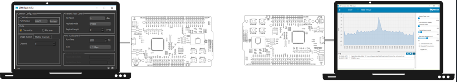
I used Direct test mode and in Transmitter tab using single channel mode. I have used used UART to set up connection with desktop and the chip.

In DTM mode we can able to transmit the power from the chip, that can be measured using at the other end with help of spectrum analyzer.

But to check received power I tried using RSSI viewer, but when I tried to connect the chip using UART it show " No pre-compiled firmware is available for the selected device"; "Error while setting up device" and "No device setup found"

My question is during DTM mode the connection with UART is established while during RSSI its shows Error messages?

What could be the reason and how to overcome?

Is there any way to measure received power in the nordic chip n52840?

Parents Reply Children
  • Hi, That is correct, for measuring RX I would reefer to this whitepaper. It described how to do a RF Performance Test, if you only want a indication I would make the DUT send the received RSSI over UART and store the data. 

    Regards

    Runar

  • Hi

    How can we transfer received RSSI over UART and store the data?

    For the measurement setup , we could use any arbitrary Continuous wave generator to act as source?

    And the receiver end would be the Our Nordic chip connected With Laptop through UART and we can able to see received Power?

  • Hi, 

    For the RSSI I would again reefer to the my initial post as they use the same example and discuss how to get the RSSI value. As for how to store the data is a bit up to your preferences. For Windows I like the tera term terminal and it has a option to store the terminal session values as a text file. Many terminals has this option, it is also possible to just mark the data from the terminal you wish to store and copy paste it into another document. 

    As for the wave generator. It needs to have modulated carrier with the correct modulation and a valid data package. The easiest solution is to use the "low cost" setup described in the white paper with a calibrated RF attenuator between a nRF52840 DK and your custom board.   

    I would recommend using the Radio Test Example, on the custom board, change the UART pins in the overlay to the UART pins in your custom board. 

    Regards

    Runar 

Related