
I am developing in VSCode on an nRF52832 and trying to get peripherals setup correctly on my device. Using the device tree beyond the examples is proving difficult. I had one little issue that I made a really hacky solution to get a button working, but now I need 7 PWM channels and in digging for he solution I have been learning more and realize that these issues are related. In the end, I am probably not setting up something right in the device tree, but I cannot spot it.
First I'll explain the issue and the hack that made it work:
I have 3 buttons on a device and one is different than the other two. Ultimately, two have pull ups and one has a pull down. They have reversed logic.
	buttons {
		compatible = "gpio-keys";
		button0: button_0 {
			gpios = <&gpio0 10 (GPIO_INPUT)>;
			label = "SW_MD";
		};
		button1: button_1 {
			gpios = <&gpio0 3 (GPIO_INPUT | GPIO_PULL_UP | GPIO_ACTIVE_LOW)>;
			label = "SW_UP";
		};
		button2: button_2 {
			gpios = <&gpio0 8 (GPIO_INPUT | GPIO_PULL_UP | GPIO_ACTIVE_LOW)>;
			label = "SW_DN";
		};
	};
Above is my current definitions. You will not that on button has no pull up or pull down defined. It has a pull down on the board. Also, this same hardware worked in project built using the NRF5 SDK.
void rem_ui_init(void)
{
	int ret;
	if (!gpio_is_ready_dt(&z_btn_u)) {
		LOG_ERR("Error: button device %s is not ready", z_btn_u.port->name);
	}
	ret = gpio_pin_configure_dt(&z_btn_u, GPIO_INPUT);
	if (ret != 0) {
		LOG_ERR("Error %d: failed to configure %s pin %d", ret, z_btn_u.port->name, z_btn_u.pin);
	}

	if (!gpio_is_ready_dt(&z_btn_d)) {
		LOG_ERR("Error: button device %s is not ready", z_btn_d.port->name);
	}
	ret = gpio_pin_configure_dt(&z_btn_d, GPIO_INPUT);
	if (ret != 0) {
		LOG_ERR("Error %d: failed to configure %s pin %d", ret, z_btn_d.port->name, z_btn_d.pin);
	}

	if (!gpio_is_ready_dt(&z_btn_m)) {
		LOG_ERR("Error: button device %s is not ready", z_btn_m.port->name);
	}
	z_btn_m.dt_flags &= ~GPIO_PULL_UP; // HACK this is somehow getting setup wrong and has the pull up flag set when it should not be set.
	ret = gpio_pin_configure_dt(&z_btn_m, GPIO_INPUT | GPIO_PULL_DOWN | GPIO_ACTIVE_HIGH);
	if (ret != 0) {
		LOG_ERR("Error %d: failed to configure %s pin %d", ret, z_btn_m.port->name, z_btn_m.pin);
	}

	LOG_INF(LOG_GREEN "Buttons initialized!");
	leds_init();
}
Above is my initialization function for the buttons. You may note that above the configuration of "z_btn_m" is a line of code that changes the flags for the GPIO by erasing the pull up flag, which should not be set in according to the device tree, but it is set. We can see in devicetree_generated.h that the flags are set to 17.
/*
 * Devicetree node: /buttons/button_2
 *
 * Node identifier: DT_N_S_buttons_S_button_2
 *
 * (Descriptions have moved to the Devicetree Bindings Index
 * in the documentation.)
 */

/* Node's full path: */
#define DT_N_S_buttons_S_button_2_PATH "/buttons/button_2"

/* Node's name with unit-address: */
#define DT_N_S_buttons_S_button_2_FULL_NAME "button_2"

/* Node parent (/buttons) identifier: */
#define DT_N_S_buttons_S_button_2_PARENT DT_N_S_buttons

/* Node's index in its parent's list of children: */
#define DT_N_S_buttons_S_button_2_CHILD_IDX 2

/* Helper macros for child nodes of this node. */
#define DT_N_S_buttons_S_button_2_FOREACH_CHILD(fn)
#define DT_N_S_buttons_S_button_2_FOREACH_CHILD_SEP(fn, sep)
#define DT_N_S_buttons_S_button_2_FOREACH_CHILD_VARGS(fn, ...)
#define DT_N_S_buttons_S_button_2_FOREACH_CHILD_SEP_VARGS(fn, sep, ...)
#define DT_N_S_buttons_S_button_2_FOREACH_CHILD_STATUS_OKAY(fn)
#define DT_N_S_buttons_S_button_2_FOREACH_CHILD_STATUS_OKAY_SEP(fn, sep)
#define DT_N_S_buttons_S_button_2_FOREACH_CHILD_STATUS_OKAY_VARGS(fn, ...)
#define DT_N_S_buttons_S_button_2_FOREACH_CHILD_STATUS_OKAY_SEP_VARGS(fn, sep, ...)

/* Node's dependency ordinal: */
#define DT_N_S_buttons_S_button_2_ORD 12

/* Ordinals for what this node depends on directly: */
#define DT_N_S_buttons_S_button_2_REQUIRES_ORDS \
	8, /* /buttons */ \
	9, /* /soc/gpio@50000000 */

/* Ordinals for what depends directly on this node: */
#define DT_N_S_buttons_S_button_2_SUPPORTS_ORDS /* nothing */

/* Existence and alternate IDs: */
#define DT_N_S_buttons_S_button_2_EXISTS 1
#define DT_N_ALIAS_sw2         DT_N_S_buttons_S_button_2
#define DT_N_NODELABEL_button2 DT_N_S_buttons_S_button_2

/* Macros for properties that are special in the specification: */
#define DT_N_S_buttons_S_button_2_REG_NUM 0
#define DT_N_S_buttons_S_button_2_RANGES_NUM 0
#define DT_N_S_buttons_S_button_2_FOREACH_RANGE(fn)
#define DT_N_S_buttons_S_button_2_IRQ_NUM 0
#define DT_N_S_buttons_S_button_2_STATUS_okay 1

/* Pin control (pinctrl-<i>, pinctrl-names) properties: */
#define DT_N_S_buttons_S_button_2_PINCTRL_NUM 0

/* Generic property macros: */
#define DT_N_S_buttons_S_button_2_P_gpios_IDX_0_EXISTS 1
#define DT_N_S_buttons_S_button_2_P_gpios_IDX_0_PH DT_N_S_soc_S_gpio_50000000
#define DT_N_S_buttons_S_button_2_P_gpios_IDX_0_VAL_pin 10
#define DT_N_S_buttons_S_button_2_P_gpios_IDX_0_VAL_pin_EXISTS 1
#define DT_N_S_buttons_S_button_2_P_gpios_IDX_0_VAL_flags 17
#define DT_N_S_buttons_S_button_2_P_gpios_IDX_0_VAL_flags_EXISTS 1
#define DT_N_S_buttons_S_button_2_P_gpios_FOREACH_PROP_ELEM(fn) fn(DT_N_S_buttons_S_button_2, gpios, 0)
#define DT_N_S_buttons_S_button_2_P_gpios_FOREACH_PROP_ELEM_SEP(fn, sep) fn(DT_N_S_buttons_S_button_2, gpios, 0)
#define DT_N_S_buttons_S_button_2_P_gpios_FOREACH_PROP_ELEM_VARGS(fn, ...) fn(DT_N_S_buttons_S_button_2, gpios, 0, __VA_ARGS__)
#define DT_N_S_buttons_S_button_2_P_gpios_FOREACH_PROP_ELEM_SEP_VARGS(fn, sep, ...) fn(DT_N_S_buttons_S_button_2, gpios, 0, __VA_ARGS__)
#define DT_N_S_buttons_S_button_2_P_gpios_LEN 1
#define DT_N_S_buttons_S_button_2_P_gpios_EXISTS 1
#define DT_N_S_buttons_S_button_2_P_label "SW_MD"
#define DT_N_S_buttons_S_button_2_P_label_STRING_TOKEN SW_MD
#define DT_N_S_buttons_S_button_2_P_label_STRING_UPPER_TOKEN SW_MD
#define DT_N_S_buttons_S_button_2_P_label_FOREACH_PROP_ELEM(fn) fn(DT_N_S_buttons_S_button_2, label, 0) \
	fn(DT_N_S_buttons_S_button_2, label, 1) \
	fn(DT_N_S_buttons_S_button_2, label, 2) \
	fn(DT_N_S_buttons_S_button_2, label, 3) \
	fn(DT_N_S_buttons_S_button_2, label, 4)
#define DT_N_S_buttons_S_button_2_P_label_FOREACH_PROP_ELEM_SEP(fn, sep) fn(DT_N_S_buttons_S_button_2, label, 0) DT_DEBRACKET_INTERNAL sep \
	fn(DT_N_S_buttons_S_button_2, label, 1) DT_DEBRACKET_INTERNAL sep \
	fn(DT_N_S_buttons_S_button_2, label, 2) DT_DEBRACKET_INTERNAL sep \
	fn(DT_N_S_buttons_S_button_2, label, 3) DT_DEBRACKET_INTERNAL sep \
	fn(DT_N_S_buttons_S_button_2, label, 4)
#define DT_N_S_buttons_S_button_2_P_label_FOREACH_PROP_ELEM_VARGS(fn, ...) fn(DT_N_S_buttons_S_button_2, label, 0, __VA_ARGS__) \
	fn(DT_N_S_buttons_S_button_2, label, 1, __VA_ARGS__) \
	fn(DT_N_S_buttons_S_button_2, label, 2, __VA_ARGS__) \
	fn(DT_N_S_buttons_S_button_2, label, 3, __VA_ARGS__) \
	fn(DT_N_S_buttons_S_button_2, label, 4, __VA_ARGS__)
#define DT_N_S_buttons_S_button_2_P_label_FOREACH_PROP_ELEM_SEP_VARGS(fn, sep, ...) fn(DT_N_S_buttons_S_button_2, label, 0, __VA_ARGS__) DT_DEBRACKET_INTERNAL sep \
	fn(DT_N_S_buttons_S_button_2, label, 1, __VA_ARGS__) DT_DEBRACKET_INTERNAL sep \
	fn(DT_N_S_buttons_S_button_2, label, 2, __VA_ARGS__) DT_DEBRACKET_INTERNAL sep \
	fn(DT_N_S_buttons_S_button_2, label, 3, __VA_ARGS__) DT_DEBRACKET_INTERNAL sep \
	fn(DT_N_S_buttons_S_button_2, label, 4, __VA_ARGS__)
#define DT_N_S_buttons_S_button_2_P_label_EXISTS 1
#define DT_N_S_buttons_S_button_2_P_zephyr_code 0
#define DT_N_S_buttons_S_button_2_P_zephyr_code_EXISTS 1
The flags from the above code is here: "DT_N_S_buttons_S_button_2_P_gpios_IDX_0_VAL_flags 17". This maps to the pull up flag being set, despite in not having been set in the device tree. My hack corrects this, but it looks like there is some sort issue in the translation of the device tree into the devicetree_generated.h file. This process is a black box to me, so I do not know how to correct it, hence the hack.
That leads me to the actual issue I need fixed and hopefully in the process I can find a solution to the issue I just described without the hack. I am setting up 7 PWM output for some LEDs. I need to use two PWM modules, 4 channels from one and only 3 from another. The 4 are white LEDs and the 3 are for an RGB LED. I am trying to use the pinctrl system as well. Below I will include some of the devicetree snippets.
leds {
		compatible = "gpio-leds";
		led0: led_0 {
			gpios = <&gpio0 28 GPIO_ACTIVE_LOW>;
			label = "LED_W0";
		};
		led1: led_1 {
			gpios = <&gpio0 29 GPIO_ACTIVE_LOW>;
			label = "LED_W1";
		};
		led2: led_2 {
			gpios = <&gpio0 9 GPIO_ACTIVE_LOW>;
			label = "LED_W2";
		};
		led3: led_3 {
			gpios = <&gpio0 12 GPIO_ACTIVE_LOW>;
			label = "LED_W3";
		};
		led4: led_4 {
			gpios = <&gpio0 7 GPIO_ACTIVE_LOW>;
			label = "LED_R";
		};
		led5: led_5 {
			gpios = <&gpio0 5 GPIO_ACTIVE_LOW>;
			label = "LED_G";
		};
		led6: led_6 {
			gpios = <&gpio0 4 GPIO_ACTIVE_LOW>;
			label = "LED_B";
		};
	};


	pwmleds {
		compatible = "pwm-leds";
		pwm_led0: pwm_led_0 {
			pwms = <&pwm0 0 PWM_MSEC(20) PWM_POLARITY_INVERTED>;
		};
		pwm_led1: pwm_led_1 {
			pwms = <&pwm0 1 PWM_MSEC(20) PWM_POLARITY_INVERTED>;
		};
		pwm_led2: pwm_led_2 {
			pwms = <&pwm0 2 PWM_MSEC(20) PWM_POLARITY_INVERTED>;
		};
		pwm_led3: pwm_led_3 {
			pwms = <&pwm0 3 PWM_MSEC(20) PWM_POLARITY_INVERTED>;
		};
		pwm_led4: pwm_led_4 {
			pwms = <&pwm1 0 PWM_MSEC(20) PWM_POLARITY_INVERTED>;
		};
		pwm_led5: pwm_led_5 {
			pwms = <&pwm1 1 PWM_MSEC(20) PWM_POLARITY_INVERTED>;
		};
		pwm_led6: pwm_led_6 {
			pwms = <&pwm1 2 PWM_MSEC(20) PWM_POLARITY_INVERTED>;
		};
	};
pwm0_default: pwm0_default {
		group1 {
			psels = <NRF_PSEL(PWM_OUT0, 0, 28)>,
					<NRF_PSEL(PWM_OUT1, 0, 29)>,
					<NRF_PSEL(PWM_OUT2, 0, 9)>,
					<NRF_PSEL(PWM_OUT3, 0, 12)>;
			nordic,invert;
		};
	};

	pwm0_sleep: pwm0_sleep {
		group1 {
			psels = <NRF_PSEL(PWM_OUT0, 0, 28)>,
					<NRF_PSEL(PWM_OUT1, 0, 29)>,
					<NRF_PSEL(PWM_OUT2, 0, 9)>,
					<NRF_PSEL(PWM_OUT3, 0, 12)>;
			low-power-enable;
		};
	};

	pwm1_default: pwm1_default {
		group1 {
			psels = <NRF_PSEL(PWM_OUT0, 0, 7)>,
					<NRF_PSEL(PWM_OUT1, 0, 5)>,
					<NRF_PSEL(PWM_OUT2, 0, 4)>;
			nordic,invert;
		};
	};

	pwm1_sleep: pwm1_sleep {
		group1 {
			psels = <NRF_PSEL(PWM_OUT0, 0, 7)>,
					<NRF_PSEL(PWM_OUT1, 0, 5)>,
					<NRF_PSEL(PWM_OUT2, 0, 4)>;
			low-power-enable;
		};
	};
As a note, I have seen in the examples both "leds" and "pwmleds" defined in the devicetree, but only "pwmleds" seems to be used. I'm assuming that those are left in the examples from the development of the examples, but like I said, that an assumption based on my failed attempts to get this working. Needless to say, I don't think that they are important, but I included them in the snippet. Starting with the first entry in the devicetree "pwmleds":
pwmleds {
		compatible = "pwm-leds";
		pwm_led0: pwm_led_0 {
			pwms = <&pwm0 0 PWM_MSEC(20) PWM_POLARITY_INVERTED>;
		};
compatible = "pwm-leds" is the way that the device tree interpreter understand how to parse the information in that section. I've dug for information about that in the past but it is hard to understand for the uninitiated.
pwm_led0: pwm_led_0 names the entry, I think the second name one is a keyword defined by "pwm_leds" but Im not sure. The first name needs to match the something in the list of aliases.
pwms = <&pwm0 0 PWM_MSEC(20) PWM_POLARITY_INVERTED>;
I believe that this is defined here: https://docs.zephyrproject.org/latest/build/dts/api/bindings/pwm/nordic%2Cnrf-pwm.html#dtbinding-nordic-nrf-pwm. I've included a screen shot below.
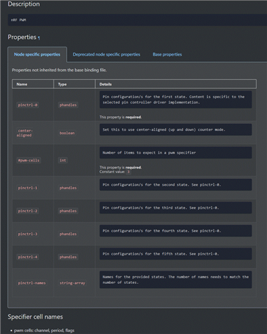
I was looking for what pwms means, and one can observe that "pwms" appears nowhere on this page. In the section "#pwm-cells" it mentions that it is a definition for the pwm specifier number of cells, so I assume that "pwms" is short for "pwm specifier" and to understand what is in those cells you have to look at what is basically an unlinked foot note that does not contain the name "pwms" or "PWM specifier" but only "Specifier Cell names". So am I correct in my assumption that this is the definition of what should be in the "pwms" cells? One last source of confusion is in "pwms" there appears to be 4 cells instead of 3 because the &pwm0 is another name. It has been my assumption that is does not count as a cell because it is a tag as opposed to the other 3 being settings for that tagged device. So if my assumptions are correct, the tag is the PWM module being modified (&pwm0). The first cell is the channel being used within that module (channel 0). The second cell is the period for the pwm (20ns). The third and final cell is whether or not to invert that pwm channel (inverted in the sample). Is my understanding correct?
Next I would like to look at the pinctrl part of the devicetree.
pwm0_default: pwm0_default {
		group1 {
			psels = <NRF_PSEL(PWM_OUT0, 0, 28)>,
					<NRF_PSEL(PWM_OUT1, 0, 29)>,
					<NRF_PSEL(PWM_OUT2, 0, 9)>,
					<NRF_PSEL(PWM_OUT3, 0, 12)>;
			nordic,invert;
		};
	};

	pwm0_sleep: pwm0_sleep {
		group1 {
			psels = <NRF_PSEL(PWM_OUT0, 0, 28)>,
					<NRF_PSEL(PWM_OUT1, 0, 29)>,
					<NRF_PSEL(PWM_OUT2, 0, 9)>,
					<NRF_PSEL(PWM_OUT3, 0, 12)>;
			low-power-enable;
		};
	};

	pwm1_default: pwm1_default {
		group1 {
			psels = <NRF_PSEL(PWM_OUT0, 0, 7)>,
					<NRF_PSEL(PWM_OUT1, 0, 5)>,
					<NRF_PSEL(PWM_OUT2, 0, 4)>;
			nordic,invert;
		};
	};

	pwm1_sleep: pwm1_sleep {
		group1 {
			psels = <NRF_PSEL(PWM_OUT0, 0, 7)>,
					<NRF_PSEL(PWM_OUT1, 0, 5)>,
					<NRF_PSEL(PWM_OUT2, 0, 4)>;
			low-power-enable;
		};
	};
From what I understand is allows the user to configure alternative configurations. I'm not yet sure how I would select on configuration or the other, but from the examples I have looked at I see a default and a sleep configuration. I believe the name links it to the actual peripherial (pwm0_default -> pwm0 in normal operation and pwm0_sleep -> pwm0 in sleep mode). I'm not really clear what "group1" accomplishes but it's in the examples. I think that "low-power-enable" and "nordic,invert" are tags that actually define how to interpret the information, but I believe "psels" is where the important stuff happens.
After some searching I found this: https://docs.zephyrproject.org/latest/build/dts/api/bindings/pinctrl/nordic%2Cnrf-pinctrl.html#dtbinding-nordic-nrf-pinctrl and it show some example code for a simple GPIO setup. It did provide a reference to this:
Available pin functions can be found in the
include/zephyr/dt-bindings/pinctrl/nrf-pinctrl.h header file.
After a bit of digging I found it:
/** @} */

/**
 * @brief Utility macro to build nRF psels property entry.
 *
 * @param fun Pin function configuration (see NRF_FUNC_{name} macros).
 * @param port Port (0 or 1).
 * @param pin Pin (0..31).
 */
#define NRF_PSEL(fun, port, pin)						       \
	((((((port) * 32U) + (pin)) & NRF_PIN_MSK) << NRF_PIN_POS) |		       \
	 ((NRF_FUN_ ## fun & NRF_FUN_MSK) << NRF_FUN_POS))
Now I know the fields, mostly. port an pin is straighforward. They are the port and pin values used to output to a pin. On my nRF52832 there is only port 0 (as opposed the thenRF52840 that had port 0 and 1), so it is simply setting the port number to 0 and the pin to match my output pin. The field "fun" is much more vague:
/** PWM OUT0 */
#define NRF_FUN_PWM_OUT0 22U
/** PWM OUT1 */
#define NRF_FUN_PWM_OUT1 23U
/** PWM OUT2 */
#define NRF_FUN_PWM_OUT2 24U
/** PWM OUT3 */
#define NRF_FUN_PWM_OUT3 25U
Just a ways above the NRF_PSEL() macro you can find the definitions, but what is an "out"? My guess is that it is the channel since there are 4 channels poer module, but the are 4 modules in the nRF52840 (I think that there are only 3 in the nRF52832). This nrf_pinctrl.h finle I am guessing is used for all nrf devices and it does not say clearly if this is for the channel, module or something else entirely. In the devicetree pwm0 I think tags the module. There is a pwm1 that I am trying to use as well. I think in pinctrl pwm0_default tags the module. But I thought that I already set the channel in the device tress in the pwms cells? SO it looks like it goes in two places, but maybe the pinctrl module overrides the devicetree defined one? I am not sure, but for now I am defining channel 0 in the devicetree and "NRF_FUN_PWM_OUT0" in pinctrl. What is best for here?
Now how does this all work when I compile and flash? It does not. The device runs, but there is not PWM output. I call "pwm_set_pulse_dt()" with a test period of one quarter the period and I see no output. I have pwm loggin on and see this output:
[00:00:00.280,639] <dbg> pwm_nrfx: pwm_nrfx_set_cycles: channel 0, pulse 80000, period 320000, prescaler: 4.
I did a similar hack as what I did to the buttons and I can get the different channels to report in the logging, but only for PWM0, but still no light output. So I dig into devicetree_generated.h.
I found that for all 7 PWMs that I setup, they all are set to channel 0 and only PWM0 seems to be used. That include the ones I setup up using &pwm1. PWM0 is at address 0x4001c000, and PWM1 is at 0x40021000. I've included definitions for channel 3 of pwm1 below:
/*
 * Devicetree node: /pwmleds/pwm_led_6
 *
 * Node identifier: DT_N_S_pwmleds_S_pwm_led_6
 *
 * (Descriptions have moved to the Devicetree Bindings Index
 * in the documentation.)
 */

/* Node's full path: */
#define DT_N_S_pwmleds_S_pwm_led_6_PATH "/pwmleds/pwm_led_6"

/* Node's name with unit-address: */
#define DT_N_S_pwmleds_S_pwm_led_6_FULL_NAME "pwm_led_6"

/* Node parent (/pwmleds) identifier: */
#define DT_N_S_pwmleds_S_pwm_led_6_PARENT DT_N_S_pwmleds

/* Node's index in its parent's list of children: */
#define DT_N_S_pwmleds_S_pwm_led_6_CHILD_IDX 6

/* Helper macros for child nodes of this node. */
#define DT_N_S_pwmleds_S_pwm_led_6_FOREACH_CHILD(fn)
#define DT_N_S_pwmleds_S_pwm_led_6_FOREACH_CHILD_SEP(fn, sep)
#define DT_N_S_pwmleds_S_pwm_led_6_FOREACH_CHILD_VARGS(fn, ...)
#define DT_N_S_pwmleds_S_pwm_led_6_FOREACH_CHILD_SEP_VARGS(fn, sep, ...)
#define DT_N_S_pwmleds_S_pwm_led_6_FOREACH_CHILD_STATUS_OKAY(fn)
#define DT_N_S_pwmleds_S_pwm_led_6_FOREACH_CHILD_STATUS_OKAY_SEP(fn, sep)
#define DT_N_S_pwmleds_S_pwm_led_6_FOREACH_CHILD_STATUS_OKAY_VARGS(fn, ...)
#define DT_N_S_pwmleds_S_pwm_led_6_FOREACH_CHILD_STATUS_OKAY_SEP_VARGS(fn, sep, ...)

/* Node's dependency ordinal: */
#define DT_N_S_pwmleds_S_pwm_led_6_ORD 61

/* Ordinals for what this node depends on directly: */
#define DT_N_S_pwmleds_S_pwm_led_6_REQUIRES_ORDS \
	53, /* /pwmleds */ \
	54, /* /soc/pwm@4001c000 */

/* Ordinals for what depends directly on this node: */
#define DT_N_S_pwmleds_S_pwm_led_6_SUPPORTS_ORDS /* nothing */

/* Existence and alternate IDs: */
#define DT_N_S_pwmleds_S_pwm_led_6_EXISTS 1
#define DT_N_ALIAS_pwm_led6     DT_N_S_pwmleds_S_pwm_led_6
#define DT_N_NODELABEL_pwm_led6 DT_N_S_pwmleds_S_pwm_led_6

/* Macros for properties that are special in the specification: */
#define DT_N_S_pwmleds_S_pwm_led_6_REG_NUM 0
#define DT_N_S_pwmleds_S_pwm_led_6_RANGES_NUM 0
#define DT_N_S_pwmleds_S_pwm_led_6_FOREACH_RANGE(fn)
#define DT_N_S_pwmleds_S_pwm_led_6_IRQ_NUM 0
#define DT_N_S_pwmleds_S_pwm_led_6_STATUS_okay 1

/* Pin control (pinctrl-<i>, pinctrl-names) properties: */
#define DT_N_S_pwmleds_S_pwm_led_6_PINCTRL_NUM 0

/* Generic property macros: */
#define DT_N_S_pwmleds_S_pwm_led_6_P_pwms_IDX_0_EXISTS 1
#define DT_N_S_pwmleds_S_pwm_led_6_P_pwms_IDX_0_PH DT_N_S_soc_S_pwm_4001c000
#define DT_N_S_pwmleds_S_pwm_led_6_P_pwms_IDX_0_VAL_channel 0
#define DT_N_S_pwmleds_S_pwm_led_6_P_pwms_IDX_0_VAL_channel_EXISTS 1
#define DT_N_S_pwmleds_S_pwm_led_6_P_pwms_IDX_0_VAL_period 20000000
#define DT_N_S_pwmleds_S_pwm_led_6_P_pwms_IDX_0_VAL_period_EXISTS 1
#define DT_N_S_pwmleds_S_pwm_led_6_P_pwms_IDX_0_VAL_flags 1
#define DT_N_S_pwmleds_S_pwm_led_6_P_pwms_IDX_0_VAL_flags_EXISTS 1
#define DT_N_S_pwmleds_S_pwm_led_6_P_pwms_FOREACH_PROP_ELEM(fn) fn(DT_N_S_pwmleds_S_pwm_led_6, pwms, 0)
#define DT_N_S_pwmleds_S_pwm_led_6_P_pwms_FOREACH_PROP_ELEM_SEP(fn, sep) fn(DT_N_S_pwmleds_S_pwm_led_6, pwms, 0)
#define DT_N_S_pwmleds_S_pwm_led_6_P_pwms_FOREACH_PROP_ELEM_VARGS(fn, ...) fn(DT_N_S_pwmleds_S_pwm_led_6, pwms, 0, __VA_ARGS__)
#define DT_N_S_pwmleds_S_pwm_led_6_P_pwms_FOREACH_PROP_ELEM_SEP_VARGS(fn, sep, ...) fn(DT_N_S_pwmleds_S_pwm_led_6, pwms, 0, __VA_ARGS__)
#define DT_N_S_pwmleds_S_pwm_led_6_P_pwms_LEN 1
#define DT_N_S_pwmleds_S_pwm_led_6_P_pwms_EXISTS 1
I can see the correct period is set, but channel 0 is set when it should be set to channel 2. You can also see that it references the address 0x4001c000 erroneously instead of 0x40021000 for PWM1. I see no refeneces to pwm1_default and I do not see any pinctrl refeneces to the pins I defined for the pwm outputs.
What I see is something is wrong with the inperpretation of my device tree into the devicetree_generated.h file. I could be misunderstadning a lot since I have made several assumptions along the way. Please correct my assumptions and help me understand how to generate the correct devicetree header.

