nRF52832 with SK6812 LEDs

Hello,

I tried to run the example code for the ws2812 (which can be found at C:\ncs\v2.4.1\v2.4.1\zephyr\samples\drivers\led_ws2812) for the nRF52832 using nRF Connect SDK (v2.4.1).

Looking at the nrf52dk_nrf52832.overlay, it looks like MOSI would be used on P0.23.

&arduino_spi { /* MOSI on D11 / P0.23 */

I am trying to experiment using the nRF52 DK board. 
I have a known working LED ring which lights up from another board.

The code builds fine but when I run it, I see the following in the terminal.
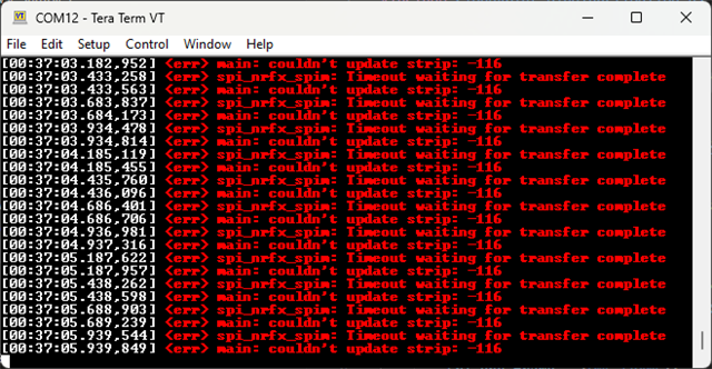
Using a Saleae Logic analyzer, I don't see anything on P0.23. 

I tried adding the following from nrf52dk_nrf52832.dts but I ended up with the same message in the terminal and didn't see anything on the logic analyzer.

I tried multiple pins and couldn't see any changes on the IO lines that looked like the required signal for the WS2812 LEDs.

&spi2_default {
    group1 {
        psels = <NRF_PSEL(SPIM_SCK, 0, 25)>, <NRF_PSEL(SPIM_MISO, 0, 24)>,
        <NRF_PSEL(SPIM_MOSI, 0, 12)>;
    };
};

/*
 * Copyright (c) 2017 Linaro Limited
 * Copyright (c) 2018 Intel Corporation
 *
 * SPDX-License-Identifier: Apache-2.0
 */

#include <errno.h>
#include <string.h>

#define LOG_LEVEL 4
#include <zephyr/logging/log.h>
LOG_MODULE_REGISTER(main);

#include <zephyr/kernel.h>
#include <zephyr/drivers/led_strip.h>
#include <zephyr/device.h>
#include <zephyr/drivers/spi.h>
#include <zephyr/sys/util.h>

#define STRIP_NODE		DT_ALIAS(led_strip)
#define STRIP_NUM_PIXELS	DT_PROP(DT_ALIAS(led_strip), chain_length)

#define DELAY_TIME K_MSEC(50)

#define RGB(_r, _g, _b) { .r = (_r), .g = (_g), .b = (_b) }

static const struct led_rgb colors[] = {
	RGB(0x0f, 0x00, 0x00), /* red */
	RGB(0x00, 0x0f, 0x00), /* green */
	RGB(0x00, 0x00, 0x0f), /* blue */
};

struct led_rgb pixels[STRIP_NUM_PIXELS];

static const struct device *const strip = DEVICE_DT_GET(STRIP_NODE);

int main(void)
{
	size_t cursor = 0, color = 0;
	int rc;

	if (device_is_ready(strip)) {
		LOG_INF("Found LED strip device %s", strip->name);
	} else {
		LOG_ERR("LED strip device %s is not ready", strip->name);
		return 0;
	}

	LOG_INF("Displaying pattern on strip");
	while (1) {
		memset(&pixels, 0x00, sizeof(pixels));
		memcpy(&pixels[cursor], &colors[color], sizeof(struct led_rgb));
		rc = led_strip_update_rgb(strip, pixels, STRIP_NUM_PIXELS);

		if (rc) {
			LOG_ERR("couldn't update strip: %d", rc);
		}

		cursor++;
		if (cursor >= STRIP_NUM_PIXELS) {
			cursor = 0;
			color++;
			if (color == ARRAY_SIZE(colors)) {
				color = 0;
			}
		}

		k_sleep(DELAY_TIME);
	}
	return 0;
}

0334.prj.conf

nrf52dk_nrf52832.dts

Has anyone had success with the WS2812 or SK6812 with the nRF52832 and nRF Connect SDK?

Thanks.

Parents Reply Children
  • Hello,

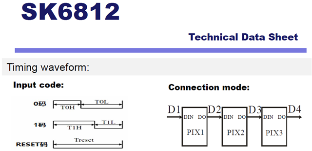
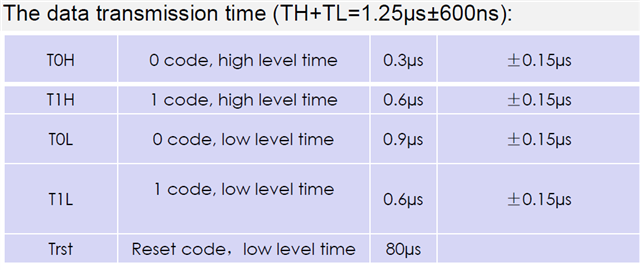
    We made our own board and use the SK6812 LEDs.  As far as I know, the SK6812  uses similar timing to the WS2812.

    Attached is the datasheet.

    Looking at this article that was referenced in the Zephyr code for working with the WS2812, the timings look very similar.

    https://wp.josh.com/2014/05/13/ws2812-neopixels-are-not-so-finicky-once-you-get-to-know-them/

    Looking at the timing on the SK6812 datasheet, to me it seems like the timing might be too short for the T1L period.

    Timing for data transmission SK6812

    What seems odd to me is that the the code looks like it should shifting in the colors such as this:

    static const struct led_rgb colors[] = {
    	RGB(0x0f, 0x00, 0x00), /* red */
    	RGB(0x00, 0x0f, 0x00), /* green */
    	RGB(0x00, 0x00, 0x0f), /* blue */
    };
    

    I changed the chain_length to a value of 1 (in nRF52dk_nrf52832.overlay)

    &pinctrl {
    	i2s0_default_alt: i2s0_default_alt {
    		group1 {
    			psels = <NRF_PSEL(I2S_SCK_M, 0, 20)>,
    				<NRF_PSEL(I2S_LRCK_M, 0, 19)>,
    				<NRF_PSEL(I2S_SDOUT, 0, 22)>, /*18 */
    				<NRF_PSEL(I2S_SDIN, 0, 21)>;  /*21 */
    		};
    	};
    };
    
    i2s_led: &i2s0 {
    	status = "okay";
    	pinctrl-0 = <&i2s0_default_alt>;
    	pinctrl-names = "default";
    };
    
    / {
    	led_strip: ws2812 {
    		compatible = "worldsemi,ws2812-i2s";
    
    		i2s-dev = < &i2s_led >;
    		chain-length = <1>; /* arbitrary; change at will */
    		color-mapping = <LED_COLOR_ID_GREEN
    					LED_COLOR_ID_RED
    					LED_COLOR_ID_BLUE>;
    		out-active-low;
    		reset-delay = <120>;
    	};
    
    	aliases {
    		led-strip = &led_strip;
    	};
    };

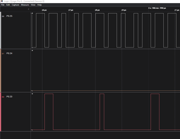
    Attached is my capture from my Saleae logic analyzer with just 1 LED in the chain length.

    SK6812 with LED Ring chain length of 1.sal

    Here is a picture of what I see.

    Logic capture of chain length of 1

    To me, this looks more like the device is transmitting 0xF0, 0xFF, 0xFF

    Looking at the code, shouldn't it be 0x0F, 0x00, 0x00.  To me, this would explain why the LED appears to be more white than anything.

    Is the device doing something to the color component that is incorrect?

  • I tried inverting the colors and that didn't seem to work either.

    SK6812 with LED Ring chain length of 12, color inverted from original code.sal

    What seems interesting, is that even inverting the colors by using

    static const struct led_rgb colors[] = {
        RGB(0xf0, 0xff, 0xff), /* red */
        RGB(0xff, 0xf0, 0xff), /* green */
        RGB(0xff, 0xff, 0xf0), /* blue */
    };

    The capture still looks it is transmitting mostly 1's.

    Attached is a video.  I dimmed it down as the LEDs are so bright.  What is strange is that the first two LEDs will be Blue, and then switch to green for the rest of the loop around the ring.  Then yellow for the first two LEDs, then switch back to green for the rest of the ring.  And then one one entire time around the ring as green.
    This is with the led_rgb colors as

    static const struct led_rgb colors[] = {
        RGB(0xf0, 0xff, 0xff), /* red */
        RGB(0xff, 0xf0, 0xff), /* green */
        RGB(0xff, 0xff, 0xf0), /* blue */
    };
  • I meant to add the capture from when I had inverted the colors and then set the chain length back to 12.

    8712.SK6812 with LED Ring chain length of 12, color inverted from original code.sal

  • Was able to test with a led strip, seems to work with SPI. 


    Video showing that the leds change. Data out pin i connected to the logic analyzer just to see what i looked like. Only needed to connect Data in for it to work. 

    Also connected to the logic analyzer and I do see some action on the lines. 


    Regards,
    Jonathan

Related