SPI with MPU9250/6000, Issue with SPI mode 3, SDK 2.4, toolchain 2.4, Zephyr 3.2

Hello, I have passed a fair amount of time doing research on how to use SPI for SDK V2.3/2.4, I manage to get somewhere using this example git project and this other example  

As of now, I am doing a bare-bones code to test spi with the mpu9250 to read the who_am_i register. 

Here is the register map of the mpu9250/6000 

Here is my prj.conf : 

CONFIG_SPI=y

here is my devicetree, to use the in i wanted for spi : 

&spi1_default {
    group1 {
        psels = <NRF_PSEL(SPIM_MISO, 1, 9)>,
                <NRF_PSEL(UART_TX, 1, 8)>,
                <NRF_PSEL(SPIM_MOSI, 1, 10)>,
                <NRF_PSEL(SPIM_SCK, 1, 11)>;
    };
};


And finally here is my main.c : 

#include <zephyr/device.h>
#include <zephyr/drivers/gpio.h>
#include <zephyr/kernel.h>
#include <zephyr/drivers/spi.h>
#include <zephyr/sys/printk.h>


#define SLEEP_TIME_MS   1000
#define WHO_AM_I_REG  0x71  //Register 117 – Who Am I, you should read the value 0x68
#define USER_CTRL  0x6A  //to disable the I2C need to write value 00010000 to this register
#define DISABLE_I2C_VAL 0x10 


#define SPI1_NODE DT_NODELABEL(spi1)
static const struct device *spi1_dev = DEVICE_DT_GET(SPI1_NODE);

#define MY_GPIO1 DT_NODELABEL(gpio1)
static const struct device *gpio1_dev = DEVICE_DT_GET(MY_GPIO1);

#define GPIO_1_CS 8 //pin for cs (chip select)  //P1.08 on dk


static struct spi_config spi_cfg ={
	.frequency = 1000 * 1000,//1M for mpu9250 
	 .operation = SPI_WORD_SET(8) | SPI_MODE_CPOL, //spi mode 3
	 //.operation = SPI_WORD_SET(8) | SPI_MODE_CPOL | SPI_MODE_CPHA, //to set SPI mode 4
	.slave = 0,
	// .cs = NULL,
};

static void readRegister (uint8_t reg, uint8_t values[], uint8_t size){
	int err;
	uint8_t tx_buffer[1];

	
	tx_buffer[0]=reg;
	//tx_buffer[1]=0x04; //use to disable i2c for now

	struct spi_buf tx_spi_bufs[] = {
		{.buf = tx_buffer, .len = sizeof(tx_buffer)},
	};
	
	struct spi_buf_set spi_tx_buffer_set = {
		.buffers = tx_spi_bufs,
		.count = 1
	};
	struct spi_buf rx_spi_bufs[] = {
		 { .buf = values, .len = size }
	};

	struct spi_buf_set spi_rx_buffer_set = {
		.buffers = rx_spi_bufs,
		.count = 1
	};

	gpio_pin_set(gpio1_dev, GPIO_1_CS, 0);

	do{
		tx_buffer[0]=reg;
		err = spi_write(spi1_dev, &spi_cfg, &spi_tx_buffer_set);
		
		 if (err < 0){
		printk("write Registers failed: %d\n", err);
		 break;
		  }

		  gpio_pin_set(gpio1_dev, GPIO_1_CS, 1);  //SINCE IT IS A 8 bit sensor, want to split into 2
			k_usleep (2);
		  gpio_pin_set(gpio1_dev, GPIO_1_CS, 0);
		  
	err = spi_read(spi1_dev, &spi_cfg, &spi_rx_buffer_set);
	if (err < 0)
		printk("Read Registers failed: %d\n", err);

	}while (false);


		gpio_pin_set(gpio1_dev, GPIO_1_CS, 1);
}


static void readreg (uint8_t reg) {
	uint8_t Ans;
	uint8_t el;
	uint8_t rx_buf_chipid[1];
	readRegister(reg, rx_buf_chipid,sizeof(rx_buf_chipid));
	Ans = rx_buf_chipid[0];
	el = rx_buf_chipid[1];
	printk("size of rx : %x\n",sizeof(rx_buf_chipid));
	printk("Reg called: 0x%x Answer: 0x%x : else : %X\n", reg,Ans,el);
}


int main(void)
{
	
 	int ret;


	ret = gpio_pin_configure (gpio1_dev, GPIO_1_CS, GPIO_OUTPUT_HIGH);
	//gpio_pin_set(gpio1_dev, GPIO_1_CS, 1); // set up as active high
	if (ret < 0) {
		printk ("Failed led Config\n");
		return;
	}
	if (!device_is_ready(spi1_dev)) {
	printk ("spil_dev not ready\n"); return;
	}


	//readreg(USER_CTRL);


	readreg(WHO_AM_I_REG);


    while (1) {
	
	}
	
	return 0;
}


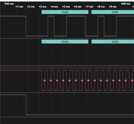
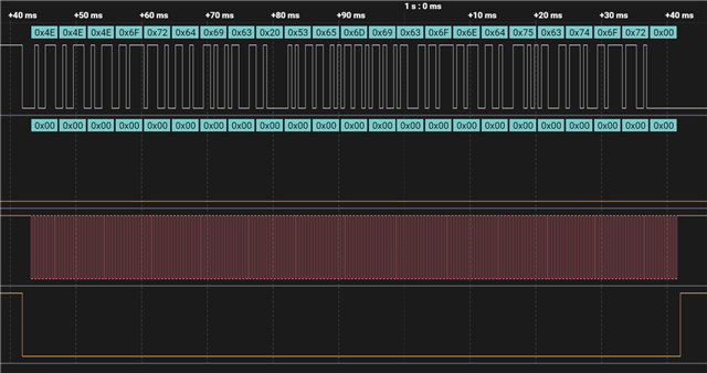
With that code i managed using a Saleae Logic analyser, on logic 2.4.1 to get those signal : 

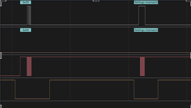
I will provide more photo if needed 
but if we compare with the datasheet

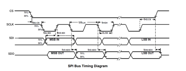
The difference are no answer from the slave + The cs goes low and after that the SPI sets in MODE 3, which I think might be a reason why it doesn't work, but only for the first time.
If you have any link and solution + example on how to implement SPI, I would be very grateful


Thank you for your time, 
Mathias

  • Hello,

    My suggestion would be to look at existing zephyr drivers using spi, or look at the test code for the spi driver:
    \zephyr\tests\drivers\spi 

    If you don't want to use the spi api, you can use the low level nrfx spim api directly:
    https://github.com/zephyrproject-rtos/hal_nordic/tree/master/nrfx/samples/src/nrfx_spim

    Kenneth

  • Hello Kenneth!, thank you for the links, I could not figure out how to make the zephyr one work, but the nrfx_spim example compiled after changing the line : 

    #include "../../../common/common-pinctrl.dtsi"  to #include "../common/common-pinctrl.dtsi"

    I then added a CS pin, a frequency <1Mhz and SPI mode 3, and its seems to write the good data : 


    ->full

    So On the Side of the nrf5340, the spi is working as expected and writing
    "NNNordic Semiconductor"

    The clock isn't acting weird anymore, so thank you.

    On the other side, I expected so random answer or anything from the sensor to see it alive, but I get nothing at all.
    If you have any idea why this could be I am 
    interested, but the Spi seems to be working at least Slight smile So it's probably on the sensor side.
    Thanks!
    main :
    
    #include <nrfx_example.h>
    #include <nrfx_spim.h>
    
    #define NRFX_LOG_MODULE                 EXAMPLE
    #define NRFX_EXAMPLE_CONFIG_LOG_ENABLED 1
    #define NRFX_EXAMPLE_CONFIG_LOG_LEVEL   3
    #include <nrfx_log.h>
    
    
    /**
     * @defgroup nrfx_spim_blocking_example Blocking SPIM example
     * @{
     * @ingroup nrfx_spim_examples
     *
     * @brief Example showing the basic functionality of nrfx_spim driver operating in the blocking mode.
     *
     * @details Application initializes nrfx_spim driver and starts operating in the blocking mode.
     *          Specified message ( @ref MSG_TO_SEND ) from @ref m_tx_buffer is transmitted and when
     *          the transfer is finished received message is read from @ref m_rx_buffer.
     */
    
    /** @brief Symbol specifying SPIM instance to be used. */
    #define SPIM_INST_IDX 1
    
    /** @brief Symbol specifying pin number for MOSI. */
    #define MOSI_PIN LOOPBACK_PIN_1A
    
    /** @brief Symbol specifying pin number for MISO. */
    #define MISO_PIN LOOPBACK_PIN_1B
    
    /** @brief Symbol specifying pin number for SCK. */
    #define SCK_PIN LOOPBACK_PIN_2A
    
    #define CS_PIN 25
    /** @brief Symbol specifying message to be sent via SPIM data transfer. */
    #define MSG_TO_SEND "NNNordic Semiconductor"
    
    /** @brief Transmit buffer initialized with the specified message ( @ref MSG_TO_SEND ). */
    static uint8_t m_tx_buffer[] = MSG_TO_SEND;
    
    
    /** @brief Receive buffer defined with the size to store specified message ( @ref MSG_TO_SEND ). */
    static uint8_t m_rx_buffer[sizeof(MSG_TO_SEND)];
    
    /**
     * @brief Function for application main entry.
     *
     * @return Nothing.
     */
    int main(void)
    {
        nrfx_err_t status;
        (void)status;
    
        NRFX_EXAMPLE_LOG_INIT();
    
        NRFX_LOG_INFO("Starting nrfx_spim basic blocking example.");
        NRFX_EXAMPLE_LOG_PROCESS();
    
        nrfx_spim_t spim_inst = NRFX_SPIM_INSTANCE(SPIM_INST_IDX);
      
    
         nrfx_spim_config_t spim_config = NRFX_SPIM_DEFAULT_CONFIG(SCK_PIN,MOSI_PIN,MISO_PIN,CS_PIN);
         spim_config.frequency = 500U*1000U;
         spim_config.mode = 3;
                                
        status = nrfx_spim_init(&spim_inst, &spim_config, NULL, NULL);
        NRFX_ASSERT(status == NRFX_SUCCESS);
    
        nrfx_spim_xfer_desc_t spim_xfer_desc = NRFX_SPIM_XFER_TRX(m_tx_buffer, sizeof(m_tx_buffer),m_rx_buffer, sizeof(m_rx_buffer));
    
        status = nrfx_spim_xfer(&spim_inst, &spim_xfer_desc, 0);
        NRFX_ASSERT(status == NRFX_SUCCESS);
    
        NRFX_LOG_INFO("Message received: %s", m_rx_buffer);
    
        NRFX_EXAMPLE_LOG_PROCESS();
    
        while (1)
        {
            NRFX_EXAMPLE_LOG_PROCESS();
        }
    }
    /** @} */
    
  • Mathias_Aavaa said:
    On the other side, I expected so random answer or anything from the sensor to see it alive, but I get nothing at all.

    Not sure if I have any suggestions, other than check that the chip is in the right mode (e.g. spi and not i2c), and that all pins are correctly (not swapped miso and mosi) and that it's sufficient powered with common ground.

    Kenneth

  • It was a problem with my sensor, it works great with another one,
    Have a great day Relaxed

Related