I want to interface the sph0645 mic in zephyr with the I2S but I am not able to do the same.
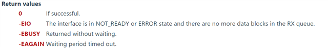
I am using the following code, because of the I2S 24 bit protocol with 32 bit word size is currently not supported in master mode by Nordic NRFX drivers. I am using the i2s as slave mode by using pwm. I am getting the error as the -11 while reading using the i2s_read() command.
#include <zephyr/zephyr.h>
#include <zephyr/device.h>
#include <zephyr/drivers/pwm.h>
#include <zephyr/drivers/i2s.h>
#include <zephyr/drivers/gpio.h>
#include <string.h>
#include <zephyr/logging/log.h>
#include <zephyr/logging/log_ctrl.h>
//#include <zephyr/pm/device.h>
#define MODULE main
#define LED0ON
#define LED1ON
LOG_MODULE_REGISTER(MODULE, 3);
#define MIC_CTRL 2
#define I2S_RX_NODE DT_NODELABEL(i2s_rx)
#define SAMPLE_FREQUENCY 44100
#define SAMPLE_BIT_WIDTH 24
#define BYTES_PER_SAMPLE sizeof(int32_t)
#define NUMBER_OF_CHANNELS 2
#define SAMPLES_PER_BLOCK ((SAMPLE_FREQUENCY / 10) * NUMBER_OF_CHANNELS)
#define INITIAL_BLOCKS 2
#define TIMEOUT 1000
/* Size of a block for 100 ms of audio data. */
#define BLOCK_SIZE(_sample_rate, _number_of_channels) \
(BYTES_PER_SAMPLE * (_sample_rate / 10) * _number_of_channels)
/* Driver will allocate blocks from this slab to receive audio data into them.
* Application, after getting a given block from the driver and processing its
* data, needs to free that block.
*/
#define MAX_BLOCK_SIZE BLOCK_SIZE(SAMPLE_FREQUENCY, 2)
#define BLOCK_COUNT 5
K_MEM_SLAB_DEFINE_STATIC(mem_slab, MAX_BLOCK_SIZE, BLOCK_COUNT, 4);
#ifdef LED0ON
static const struct pwm_dt_spec pwm_led0 = PWM_DT_SPEC_GET(DT_ALIAS(pwm_led0));
#endif
#ifdef LED1ON
static const struct pwm_dt_spec pwm_led1 = PWM_DT_SPEC_GET(DT_ALIAS(pwm_led1));
#endif
#define MIN_PERIOD PWM_SEC(1U) / 128U
#define MAX_PERIOD PWM_SEC(1U)
// LOG_MODULE_REGISTER(Recording, LOG_LEVEL_DBG);
K_THREAD_STACK_DEFINE(recording_thread_stack, 20000);
static const struct device *mic = DEVICE_DT_GET(I2S_RX_NODE);
static K_SEM_DEFINE(enable_recording, 1, 1);
static bool recording_active=false;
static struct k_thread recording_thread;
static k_tid_t worker_thread_id ;
void mic_worker_thread(void *p1, void *p2, void *p3) ;
int ret;
void recording_init() {
if (!device_is_ready(mic)) {
LOG_INF("Microphone device is not supported : %s", mic->name);
return;
}
struct i2s_config config = {
.word_size= SAMPLE_BIT_WIDTH,
.channels = NUMBER_OF_CHANNELS,
.format = I2S_FMT_DATA_FORMAT_I2S,
.options = I2S_OPT_BIT_CLK_MASTER | I2S_OPT_FRAME_CLK_MASTER,
.frame_clk_freq = SAMPLE_FREQUENCY, /* Sampling rate */
.mem_slab = &mem_slab,/* Memory slab to store rx/tx data */
.block_size = MAX_BLOCK_SIZE,/* size of memory buffer in bytes */
.timeout = TIMEOUT, /* Number of milliseconds to wait in case Tx queue is full or RX queue is empty, or 0, or SYS_FOREVER_MS */
};
//62.3 KHz dso
int err = i2s_configure(mic, I2S_DIR_RX, &config);
i2s_trigger(mic, I2S_DIR_RX, I2S_TRIGGER_PREPARE);
k_sleep(K_MSEC(100));
if (err < 0) {
LOG_ERR("Failed to initialize Microphone (%d)", err);
return;
}
k_sem_take(&enable_recording, K_FOREVER);
LOG_INF("Recording module initialized");
worker_thread_id = k_thread_create(&recording_thread, recording_thread_stack,
K_THREAD_STACK_SIZEOF(recording_thread_stack),
mic_worker_thread,
NULL, NULL, NULL,
4, 0, K_NO_WAIT);
}
void start_recording() {
recording_active = true;
// Initialize file for recording.
int ret = i2s_trigger(mic, I2S_DIR_RX, I2S_TRIGGER_START);
if (ret) {
LOG_ERR("Unable to configure trigger start for I2S bus (%d)", ret);
return;
}
k_sem_give(&enable_recording);
}
void stop_recording() {
recording_active = false;
LOG_INF("Stopping recording");
int ret = i2s_trigger(mic, I2S_DIR_RX, I2S_TRIGGER_STOP);
if (ret) {
LOG_ERR("Unable to stop trigger for I2S bus (%d)", ret);
}
k_sem_take(&enable_recording, K_FOREVER);
}
void mic_worker_thread(void *p1, void *p2, void *p3) {
LOG_INF("Worker thread started");
void* rx_buffer;
size_t bytes_read;
while (k_sem_take(&enable_recording, K_FOREVER) == 0) {
bytes_read=0;
int ret=0;
if (k_mem_slab_alloc(&mem_slab, &rx_buffer, K_MSEC(200)) == 0) {
ret = i2s_read(mic, &rx_buffer, &bytes_read);
if (ret < 0) {
if ( ret != -5) {
LOG_INF("Worker thread error (%d)\r\n", ret);
}
} else {
LOG_INF(" raw rx: %d - Received %d bytes => %d samples ", ((uint32_t *)rx_buffer)[0], bytes_read, bytes_read / sizeof(uint32_t));
}
k_mem_slab_free(&mem_slab, &rx_buffer);
}
k_sem_give(&enable_recording);
}
LOG_INF("Worker thread ended");
}
void main(){
uint32_t max_period;
uint32_t period;
uint8_t dir = 0U;
int ret;
// period = (1000000/freq);
uint32_t period1 = period*64;
LOG_INF("Starting main thread\n\r");
recording_init();
const struct device *mic_ctrl_dev = device_get_binding("GPIO_0");
gpio_pin_configure(mic_ctrl_dev,MIC_CTRL,GPIO_OUTPUT);
int pin = gpio_pin_set(mic_ctrl_dev,MIC_CTRL,1);
LOG_INF("%d", pin);
#ifdef LED0ON
if (!device_is_ready(pwm_led0.dev)) {
LOG_INF("Error: PWM device %s is not ready",
pwm_led0.dev->name);
return;
}
#endif
#ifdef LED1ON
if (!device_is_ready(pwm_led1.dev)) {
LOG_INF("Error: PWM device %s is not ready",
pwm_led1.dev->name);
return;
}
#endif
while(1) {
#ifdef LED0ON
LOG_INF("GREEN LED");
//static inline int pwm_set_dt(const struct pwm_dt_spec *spec, uint32_t period, uint32_t pulse)
ret = pwm_set_dt(&pwm_led0, period, period / 2U); //
if (ret) {
LOG_INF("Error %d: failed to set pulse width", ret);
return;
}
//k_sleep(K_SECONDS(4U));
//ret = pwm_set_dt(&pwm_led0, period, 0);
#endif
#ifdef LED1ON
LOG_INF("BLUE LED");
//static inline int pwm_set_dt(const struct pwm_dt_spec *spec, uint32_t period, uint32_t pulse)
ret = pwm_set_dt(&pwm_led1, period1, period1 / 2U);
if (ret) {
LOG_INF("Error %d: failed to set pulse width", ret);
return;
}
//k_sleep(K_SECONDS(4U));
//ret = pwm_set_dt(&pwm_led1, period1, 0);
#endif
LOG_INF("Start recording again\r\n");
start_recording();
k_sleep(K_MSEC(2000));
LOG_INF("Stop recording again\r\n");
stop_recording();
k_sleep(K_MSEC(2000));
}
}
I would like any insight into what I'm missing and how I can get this to work. Thank you for your patience and support.