I have ordered Thingy 91 in order to practise with nRF9160.
Some important information:
I am using:
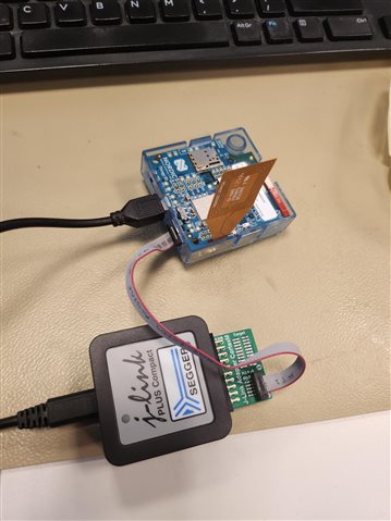
- Thingy 91
- Segger J-Link programmer to program nRF9160 and nRF52840 on the Thingy 91
- NCS v2.5.0
When I want to flash the nRF9160, I just put the SW2 in the nRF91 position and flash it with segger J-Link via vscode.
When I want to flash the nRF52840, I just put the SW2 in the nRF52840 position and flash it with segger J-Link via vscode.
About my project:
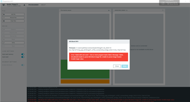
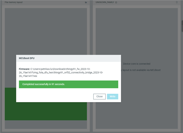
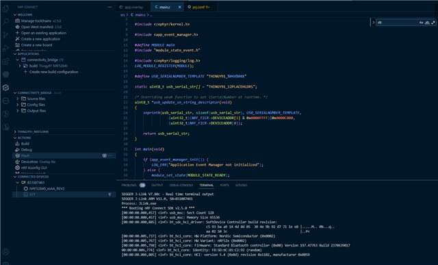
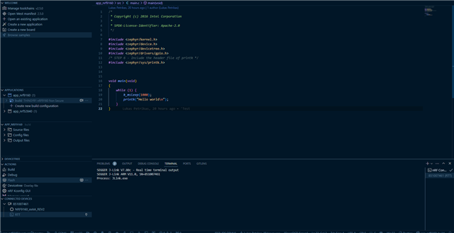
I am aware that the Thingy 91 comes with a preflashed Asset tracker v2 application. In my case, I am not interested in none of that. I have reflashed the nRF52840 with connectivity bridge application and reflashed the nRF9160 with simple "hello world" application. I have just modified it slightly to print hello world in an infinite loop. The first thing I want to test is if I am able to see the printk messages on the console as that is always the first thing I setup when working on a project.
void main(void)
{
	while (1) {
        k_msleep(1000);
		printk("Hello world\n");
	}
}
Problem:
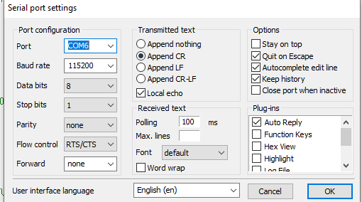
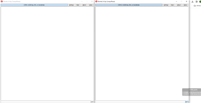
After I power the device, I can see 2 Serial ports appear. That is expected for the Connectivity Bridge application. I have opened both serial ports via serial terminal but I am not able to see any logs. I was under the impression that Conncetivity bridge application running on nRF52840 should forward all the printk messages of the nRF9160 device to one of the serial ports that appeared. Is that not the case?
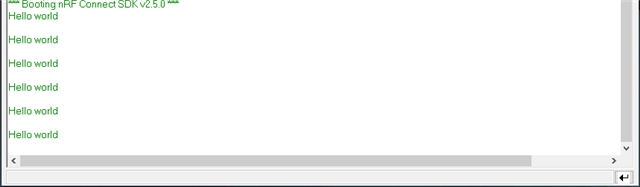
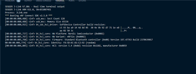
I have also tried to monitor of messages from the nRF9160 (hello world) are printing on the RTT but that is also not the case:
I have also checked the following video:
https://www.youtube.com/watch?v=0xl45L2tdcc&ab_channel=drselim
On the video above, a guy just programs a simple program to nRF9160 and he is able to see the serial messages on the serial console. The only thing that is not fully clear - what is running on the nRF52840?
I have also looked at hardware files (schematic) of the Thingy 91 and could not find anything regarding UART.
I would appreciate if someone could help me understand how to get any printk messages to show from nRF9160 and whether I need to use special firmware on nRF52840 to get this to work because connectivity bridge does not seem to work. If there is anything else you would like me to clarify, feel free to ask! Thanks in advance.