Hello. I want to write my own driver for the SPI accelerometer (ADXL362).
Sadly, there is barely any information regarding the SPI, at least it is not easily available. I have gone through various documentation regarding SPI:
https://docs.zephyrproject.org/latest/hardware/peripherals/spi.html
About my setup:
- Development board used: Thingy 91
- Logic Analyzer used: Salae logic pro 8
- External programmer/debugger used: Segger J-Link compact plus
See image of my setup (I know it looks a bit chaotic):
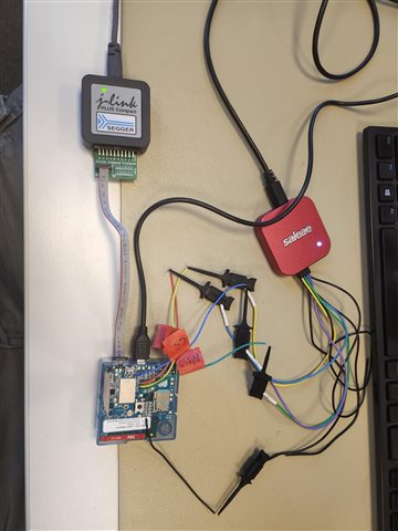
As you can see from image above, I have soldered wires on the CS, MOSI, MISO and CLK and GND testpoints so I can connect logic analyzer.
Currently I am practising using spi_write.
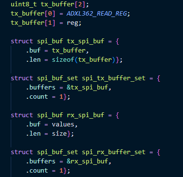
See my code below:
#include <stdio.h>
#include <stdlib.h>
#include <zephyr/kernel.h>
#include <zephyr/drivers/spi.h>
#include <zephyr/drivers/sensor.h>
#include <zephyr/drivers/gpio.h>
#include <zephyr/device.h>


#define LOG_LEVEL CONFIG_LOG_DEFAULT_LEVEL
#include <zephyr/logging/log.h>
LOG_MODULE_REGISTER(main);


#define SPI_MESSAGE 0xA5


#define DEFAULT_ADXL362_NODE DT_ALIAS(adxl362)
BUILD_ASSERT(DT_NODE_HAS_STATUS(DEFAULT_ADXL362_NODE, okay),
			 "ADXL362 not specified in DT");

//DEVICE TREE STRUCTURE
const struct device *const adxl1362_sens = DEVICE_DT_GET(DEFAULT_ADXL362_NODE);

//CHIP SELECT CONTROL
struct spi_cs_control ctrl = SPI_CS_CONTROL_INIT(DT_NODELABEL(adxl362), 2);

//SPI CONFIG
static const struct spi_config spi_cfg = {
	.operation = SPI_WORD_SET(8) | SPI_TRANSFER_MSB,
	.frequency = 4000000, // 8 mhz
	.slave = 0,
    .cs = &ctrl,
};

int main(void)
{
	int ret;
	if (!device_is_ready(adxl1362_sens))
	{
		LOG_INF("sensor: device %s not ready.\n", adxl1362_sens->name);
		return 0;
	}
	uint8_t cmd = SPI_MESSAGE;
	struct spi_buf tx_buf = {.buf = &cmd, .len = 1};
	struct spi_buf_set tx_bufs = {.buffers = &tx_buf, .count = 1};
	while (1) {
		LOG_INF("SPI writing test data \n");
		spi_write(adxl1362_sens, &spi_cfg, &tx_bufs);
		k_sleep(K_MSEC(1000));
	}

	return 0;
}
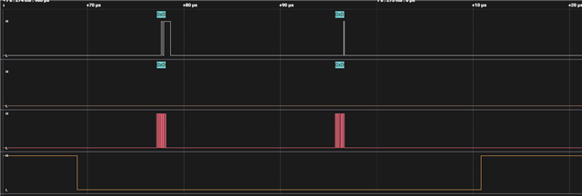
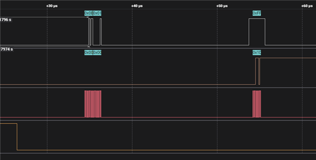
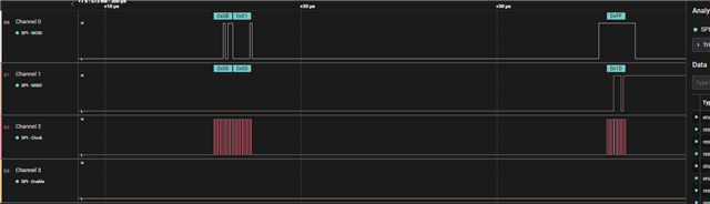
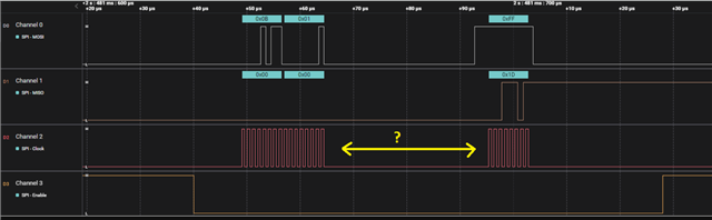
As you can see from the code above, I am expecting to send a simple SPI message periodically (every 1 second). But when I monitor signal using logic analyzer, it looks really weird:
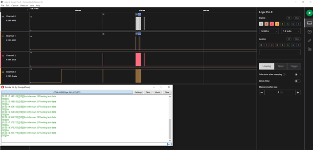
It sends some garbage once and then never again so it does not work as expected. I believe it has to do something with the chip select as it stays HIGH.
Is below correct way to initialize spi_config with chip select? How does SPI_CS_CONTROL_INIT(DT_NODELABEL(adxl362), 2); know which CS gpio to select because there are 2 chip selects declared for the SPI3 in the device tree? How does it select whether gpio0 7 or gpio0 8 is used?
struct spi_cs_control ctrl = SPI_CS_CONTROL_INIT(DT_NODELABEL(adxl362), 2);

//SPI CONFIG
static const struct spi_config spi_cfg = {
	.operation = SPI_WORD_SET(8) | SPI_TRANSFER_MSB,
	.frequency = 4000000, // 8 mhz
	.slave = 0,
    .cs = &ctrl,
};
In the nrf/boards/arm/thingy91_nrf9160/thingy91_nrf9160_common.dts the following is declared:
&spi3 {
	compatible = "nordic,nrf-spim";
	status = "okay";
	cs-gpios = <&gpio0 8 GPIO_ACTIVE_LOW>, <&gpio0 7 GPIO_ACTIVE_LOW>;

	pinctrl-0 = <&spi3_default>;
	pinctrl-1 = <&spi3_sleep>;
	pinctrl-names = "default", "sleep";
	adxl362: adxl362@0 {
		compatible = "adi,adxl362";
		spi-max-frequency = <8000000>;
		reg = <0>;
		int1-gpios = <&gpio0 9 0>;
	};

	adxl372: adxl372@1 {
		compatible = "adi,adxl372";
		spi-max-frequency = <8000000>;
		reg = <1>;
		int1-gpios = <&gpio0 6 0>;
	};
};
I am attaching Salae capture file below:
I would very much appreciate if someone could point me in the right direction. Perhaps you can spot an issue in my code? Why simple spi_write would not work ?
If you think I have missed some information or I need to clarify something, do not hesitate to ask me.
UPDATE
I have added some additional logs :
		err = spi_write(adxl1362_sens, &spi_cfg, &tx_bufs);
		if (err) {
			LOG_ERR("SPI write failed with error %d\n", err);
			return err;
		}
The logs: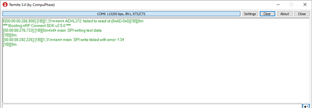
What is also very interesting, is that the device is spitting the log <err> ADXL372: failed to read id (0xAD:0x0)[1B][0m
which is very strange. In my code, I do nothing related to ADXL372. I only use ADXL362. Why would it print this error related to ADXL372?
Also, I have looked at zephyr errno documentation:
https://docs.zephyrproject.org/apidoc/latest/errno_8h.html
I have discovered that error -134 corresponds to ENOTSUP

but sadly that does not provide any useful information for me.
So to summarise everything up:
1. What is the correct way to configure spi_cs_control? Is method that I used correct?
2. Why I am getting SPI write failed with error -134? Could that be related to the Chip select?
3. Why I am getting the following printed on the console:
[00:00:00.266,723] [1B][1;31m<err> ADXL372: failed to read id (0xAD:0x0)[1B][0m.
As you have seen from my code that I posted above, it has nothing to do with ADXL372