nrf52805: ADC polling mode issue

Hardware setup: Custom board using BC805M-P (with App protect)
Software: nrf5 SDK S112 v17.0.2 ->Segger V7.30

My Objective: 

measure the Li-ion battery voltage(4.2V -100% till 3.6V-0%) through an external resistive divider & internal 0.6v ref voltage. (I'm not worried about the current consumption as of this moment. would like to make this concept work & all the other optimisations shall see later. Regarding optimisations yes I'm aware of this page: https://devzone.nordicsemi.com/nordic/nordic-blog/b/blog/posts/measuring-lithium-battery-voltage-with-nrf52)
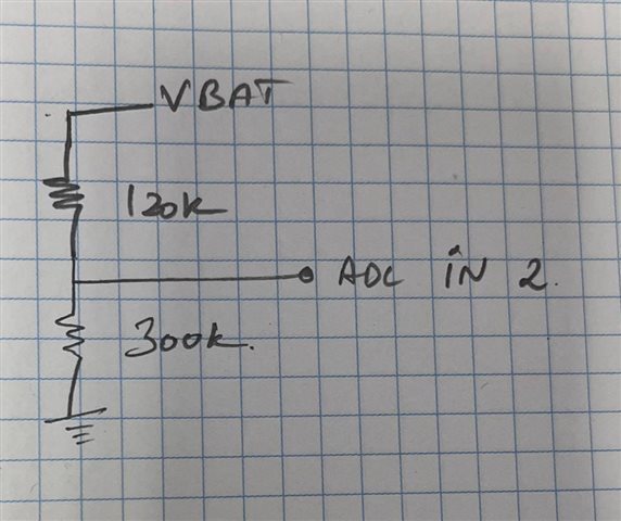
What works so far?
for the moment my example measured voltage value is being transmitted over BLE through the battery service. it's all working well.
But the ADC is just measuring some garbage value (random) which is clearly not correct.

My concept of ADC polling mode is taken from this post & modified for my work. https://devzone.nordicsemi.com/f/nordic-q-a/14486/measuring-the-battery-voltage-with-nrf52832/129422

// Input range of External Vdd measurement = (0.6 V)/(1/5) = 3 V
// 3.0 volts ->  16383 ADC counts with 14-bit sampling:  5461 counts per volt
// 3.0 volts ->  4095 ADC counts with 12-bit sampling:  1365 counts per volt

#define ADC12_COUNTS_PER_VOLT 5461

void Adc12bitPolledInitialise(void)
{
    uint32_t timeout = 10;
    nrf_saadc_channel_config_t myConfig =
    {
        .resistor_p = NRF_SAADC_RESISTOR_DISABLED,
        .resistor_n = NRF_SAADC_RESISTOR_DISABLED,
        .gain       = NRF_SAADC_GAIN1_5,            // (1/5) Gain
        .reference  = NRF_SAADC_REFERENCE_INTERNAL, // 0.6V internal Ref Voltage
        .acq_time   = NRF_SAADC_ACQTIME_40US,       // See max source resistancetable
        .mode       = NRF_SAADC_MODE_SINGLE_ENDED,
        .burst      = NRF_SAADC_BURST_DISABLED,
        .pin_p      = NRF_SAADC_INPUT_AIN2,         // AIN2 for input Pin
        .pin_n      = NRF_SAADC_INPUT_DISABLED
    };

    nrf_saadc_resolution_set((nrf_saadc_resolution_t) 3);   // 2 is 12-bit , 3 for 14-bit 
    nrf_saadc_oversample_set((nrf_saadc_oversample_t) 2);   // 2 is 4x, about 150uSecs total
    nrf_saadc_int_disable(NRF_SAADC_INT_ALL);
    nrf_saadc_event_clear(NRF_SAADC_EVENT_END);
    nrf_saadc_event_clear(NRF_SAADC_EVENT_STARTED);
    nrf_saadc_enable();

    NRF_SAADC->CH[1].CONFIG =
              ((myConfig.resistor_p << SAADC_CH_CONFIG_RESP_Pos)   & SAADC_CH_CONFIG_RESP_Msk)
            | ((myConfig.resistor_n << SAADC_CH_CONFIG_RESN_Pos)   & SAADC_CH_CONFIG_RESN_Msk)
            | ((myConfig.gain       << SAADC_CH_CONFIG_GAIN_Pos)   & SAADC_CH_CONFIG_GAIN_Msk)
            | ((myConfig.reference  << SAADC_CH_CONFIG_REFSEL_Pos) & SAADC_CH_CONFIG_REFSEL_Msk)
            | ((myConfig.acq_time   << SAADC_CH_CONFIG_TACQ_Pos)   & SAADC_CH_CONFIG_TACQ_Msk)
            | ((myConfig.mode       << SAADC_CH_CONFIG_MODE_Pos)   & SAADC_CH_CONFIG_MODE_Msk)
            | ((myConfig.burst      << SAADC_CH_CONFIG_BURST_Pos)  & SAADC_CH_CONFIG_BURST_Msk);

    NRF_SAADC->CH[1].PSELN = myConfig.pin_n;
    NRF_SAADC->CH[1].PSELP = myConfig.pin_p;
}

void ble_Update_BatteryVoltage(void)
{
    // Enable command & Turn on the Power
    nrf_gpio_pin_write(ADC_SWITCH, 1); //turning on the voltage bridge on with a transistor
    nrf_saadc_enable();

    uint16_t result = 9999;         // Some recognisable dummy value
    uint32_t timeout = 100000;       // Trial and error
    volatile int16_t buffer[8];

    NRF_SAADC->RESULT.PTR = (uint32_t)buffer;
    NRF_SAADC->RESULT.MAXCNT = 1;

    nrf_saadc_event_clear(NRF_SAADC_EVENT_END);
    nrf_saadc_task_trigger(NRF_SAADC_TASK_START);
    nrf_saadc_task_trigger(NRF_SAADC_TASK_SAMPLE);

    if (timeout != 0)
    {
        result = ((buffer[0] * 1000L)+(ADC12_COUNTS_PER_VOLT/
        5)) / ADC12_COUNTS_PER_VOLT;
    }

    while (0 == nrf_saadc_event_check(NRF_SAADC_EVENT_END) && timeout > 0)
    {
        timeout--;
    }
    nrf_saadc_task_trigger(NRF_SAADC_TASK_STOP);
    nrf_saadc_event_clear(NRF_SAADC_EVENT_STARTED);
    nrf_saadc_event_clear(NRF_SAADC_EVENT_END);

    // Disable command & turn off the Power to ADC Bridge to reduce power consumption
    nrf_saadc_disable();
    
    nrf_gpio_pin_write(ADC_SWITCH, 0); //turning off the voltage bridge on with a transistor
    ble_bas_battery_level_update(&m_bas, result, m_conn_handle); 
}


The ADC result value is clearly not accurately working when I'm just calling the function manually upon a button press. ble_Update_BatteryVoltage();

What am I doing wrong?

Thanks, for any valuable input I'm new to NRF. 
Gokunath 

Parents
  • Hi Gokulnath,

    My Objective: 

    measure the Li-ion battery voltage(4.2V -100% till 3.6V-0%) through an external resistive divider & internal 0.6v ref voltage. (I'm not worried about the current consumption as of this moment. would like to make this concept work & all the other optimisations shall see later

    You could try the peripheral/saadc sample in nRF5 SDK.

    But the ADC is just measuring some garbage value (random) which is clearly not correct.

    What does this look like? Would you be able to provide an example? Does the this change if you change the voltage?

    Thanks, for any valuable input I'm new to NRF. 

    nRF Connect SDK is recommended for new designs. Please see the nRF Connect SDK and nRF5 SDK statement as well as the nRF Connect SDK Fundamentals course at Nordic Developer Academy.

    https://www.nordicsemi.com/Products/Development-software/nrf-connect-sdk

    Here are some samples for nRF Connect SDK. You could start with simple_blocking or simple_nonblocking: hal_nordic/nrfx/samples/src/nrfx_saadc at master · zephyrproject-rtos/hal_nordic · GitHub

  • There is a bug here, the result is read before the SAADC sample has completed:

        if (timeout != 0)
        {
            result = ((buffer[0] * 1000L)+(ADC12_COUNTS_PER_VOLT/
            5)) / ADC12_COUNTS_PER_VOLT;
        }
    
        while (0 == nrf_saadc_event_check(NRF_SAADC_EVENT_END) && timeout > 0)
        {
            timeout--;
        }

    Change to:

        while (0 == nrf_saadc_event_check(NRF_SAADC_EVENT_END) && timeout > 0)
        {
            timeout--;
        }
        if (timeout != 0)
        {
            result = ((buffer[0] * 1000L)+(ADC12_COUNTS_PER_VOLT/
            5)) / ADC12_COUNTS_PER_VOLT;
        }

  • Hey,

    I've made these suggested changes. 

    Ofc the value oscillation is better than before but still, it moves a lot.

    ->My voltage bridge is always on for this particular test & I verified it on the Circuit level during operation

    My new code below:

    // Input range of internal Vdd measurement = (0.6 V)/(1/5) = 3 V
    // 3.0 volts ->  16383 ADC counts with 14-bit sampling:  5461 counts per volt
    // 3.0 volts ->  4095 ADC counts with 14-bit sampling:  1365 counts per volt
    
    #define ADC12_COUNTS_PER_VOLT 5461
    
    void Adc12bitPolledInitialise(void)
    {
        uint32_t timeout = 10;
        nrf_saadc_channel_config_t myConfig =
        {
            .resistor_p = NRF_SAADC_RESISTOR_DISABLED,
            .resistor_n = NRF_SAADC_RESISTOR_DISABLED,
            .gain       = NRF_SAADC_GAIN1_5,            // (1/5) Gain
            .reference  = NRF_SAADC_REFERENCE_INTERNAL, // 0.6V internal Ref Voltage
            .acq_time   = NRF_SAADC_ACQTIME_40US,       // See max source resistancetable
            .mode       = NRF_SAADC_MODE_SINGLE_ENDED,
            .burst      = NRF_SAADC_BURST_DISABLED,
            .pin_p      = NRF_SAADC_INPUT_AIN2,         // AIN2 for input Pin
            .pin_n      = NRF_SAADC_INPUT_DISABLED
        };
    
        nrf_saadc_resolution_set((nrf_saadc_resolution_t) 3);   // 2 is 12-bit , 3 for 14-bit 
        //nrf_saadc_oversample_set((nrf_saadc_oversample_t) 2);   // 2 is 4x, about 150uSecs total
        nrf_saadc_int_disable(NRF_SAADC_INT_ALL);
        nrf_saadc_event_clear(NRF_SAADC_EVENT_END);
        nrf_saadc_event_clear(NRF_SAADC_EVENT_STARTED);
        nrf_saadc_enable();
    
        NRF_SAADC->CH[1].CONFIG =
                  ((myConfig.resistor_p << SAADC_CH_CONFIG_RESP_Pos)   & SAADC_CH_CONFIG_RESP_Msk)
                | ((myConfig.resistor_n << SAADC_CH_CONFIG_RESN_Pos)   & SAADC_CH_CONFIG_RESN_Msk)
                | ((myConfig.gain       << SAADC_CH_CONFIG_GAIN_Pos)   & SAADC_CH_CONFIG_GAIN_Msk)
                | ((myConfig.reference  << SAADC_CH_CONFIG_REFSEL_Pos) & SAADC_CH_CONFIG_REFSEL_Msk)
                | ((myConfig.acq_time   << SAADC_CH_CONFIG_TACQ_Pos)   & SAADC_CH_CONFIG_TACQ_Msk)
                | ((myConfig.mode       << SAADC_CH_CONFIG_MODE_Pos)   & SAADC_CH_CONFIG_MODE_Msk)
                | ((myConfig.burst      << SAADC_CH_CONFIG_BURST_Pos)  & SAADC_CH_CONFIG_BURST_Msk);
    
        NRF_SAADC->CH[1].PSELN = myConfig.pin_n;
        NRF_SAADC->CH[1].PSELP = myConfig.pin_p;
        nrf_gpio_pin_write(ADC_SWITCH, 1); //Turning on  the voltage divider with a transistor
    }
    
    void ble_Update_BatteryVoltage(void)
    {
        // Enable command & Turn on the Power
        //nrf_gpio_pin_write(ADC_SWITCH, 1); //Turning on  the voltage divider with a transistor
        nrf_saadc_enable();
    
        uint16_t result = 9999;         // Some recognisable dummy value
        uint32_t timeout = 100000;       // Trial and error
        volatile int16_t buffer[100];
    
        NRF_SAADC->RESULT.PTR = (uint32_t)buffer;
        NRF_SAADC->RESULT.MAXCNT = 1;
    
        nrf_saadc_event_clear(NRF_SAADC_EVENT_END);
        nrf_saadc_task_trigger(NRF_SAADC_TASK_START);
        nrf_saadc_task_trigger(NRF_SAADC_TASK_SAMPLE);
    
        while (0 == nrf_saadc_event_check(NRF_SAADC_EVENT_END) && timeout > 0)
        {
            timeout--;
        }
    
        if (timeout != 0)
        {
            result = ((buffer[0] * 1000L)+(ADC12_COUNTS_PER_VOLT/2)) / ADC12_COUNTS_PER_VOLT;
        }
    
        nrf_saadc_task_trigger(NRF_SAADC_TASK_STOP);
        nrf_saadc_event_clear(NRF_SAADC_EVENT_STARTED);
        nrf_saadc_event_clear(NRF_SAADC_EVENT_END);
    
        // Disable command & turn off the Power to ADC Bridge to reduce power consumption
        nrf_saadc_disable();
        
        //nrf_gpio_pin_write(ADC_SWITCH, 0); //Turning off the voltage divider transistor
        ble_bas_battery_level_update(&m_bas, result, m_conn_handle); 
    }


    Regarding the example output which you asked  

    I've just parsed the output of the Battery for each button press on the BLE terminal into the txt file for simpler understanding. (All the numbers are in hex format)

    What does this look like? Would you be able to provide an example? Does the this change if you change the voltage?

    Voltage on BLE // 4.11V on voltage divider input from a Bench Power supply.
    I      0BLEParserBase.CopyToRawData:Data:0x76
    I      0BLEParserBase.CopyToRawData:Data:0x79
    I      0BLEParserBase.CopyToRawData:Data:0x89
    I      0BLEParserBase.CopyToRawData:Data:0x73
    I      0BLEParserBase.CopyToRawData:Data:0x75
    I      0BLEParserBase.CopyToRawData:Data:0x75
    I      0BLEParserBase.CopyToRawData:Data:0x7A
    I      0BLEParserBase.CopyToRawData:Data:0x6B
    I      0BLEParserBase.CopyToRawData:Data:0x75
    I      0BLEParserBase.CopyToRawData:Data:0x7B
    I      0BLEParserBase.CopyToRawData:Data:0x7E
    I      0BLEParserBase.CopyToRawData:Data:0x78
    
    Voltage on BLE // 3.68V on voltage divider input from  a Bench Power supply.
    
    I      0BLEParserBase.CopyToRawData:Data:0x4C
    I      0BLEParserBase.CopyToRawData:Data:0x40
    I      0BLEParserBase.CopyToRawData:Data:0x4B
    I      0BLEParserBase.CopyToRawData:Data:0x4B
    I      0BLEParserBase.CopyToRawData:Data:0x4A
    I      0BLEParserBase.CopyToRawData:Data:0x4B
    I      0BLEParserBase.CopyToRawData:Data:0x48
    I      0BLEParserBase.CopyToRawData:Data:0x46
    I      0BLEParserBase.CopyToRawData:Data:0x4A
    I      0BLEParserBase.CopyToRawData:Data:0x40
    I      0BLEParserBase.CopyToRawData:Data:0x45
    I      0BLEParserBase.CopyToRawData:Data:0x4B
    I      0BLEParserBase.CopyToRawData:Data:0x4D
    

    My Observations:
    I could see the Voltage on BLE clearly moves to the changes in input, My question is why it's not as stable as the bare-metal saadc example when I access it on the above polling method when the input voltage is constant?  


    My other trials:
    I've tried the default saadc peripheral example from the SDK 17.0.2 /17.1 
    It outputs the value stable on the 52DK via uart. it also responds to the changes to the input voltage accurately.

    But when I add the same code with the BLE stack the output has the same oscillation issue as mentioned in the above output text.

    Thanks for your inputs. 

  • BLE transmissions require current bursts, and even small such current bursts load the battery and are observable as voltage dips due to internal battery impedance which show up as disturbances in the measured voltage readings. Several options to reduce these voltage measurement dips: 1) sample the SAADC prior to a BLE burst (see Radio events); 2) add a filter capacitor between ADC IN 2 (AIN) and GND eg 100nF or more. Time constant of 100nF with 120k to battery is 12mSec, but for battery measurement probably an even slower value would be acceptable. The bigger the capacitor, the more even the voltage readings. 3) Use averaging; averaging is always better and for battery capacity response time is not significant.

    Often two battery indications are required; battery voltage for capacity and lowest voltage dip for pending reset or brownout problems. Use averaging for the former and single values for the latter. Maybe even use 2 SAADC inputs, one with filter capacitor and one not to allow both fast sampling via comparator or SAADC and one for slower voltage measurement for capacity, probably overkill.

Reply
  • BLE transmissions require current bursts, and even small such current bursts load the battery and are observable as voltage dips due to internal battery impedance which show up as disturbances in the measured voltage readings. Several options to reduce these voltage measurement dips: 1) sample the SAADC prior to a BLE burst (see Radio events); 2) add a filter capacitor between ADC IN 2 (AIN) and GND eg 100nF or more. Time constant of 100nF with 120k to battery is 12mSec, but for battery measurement probably an even slower value would be acceptable. The bigger the capacitor, the more even the voltage readings. 3) Use averaging; averaging is always better and for battery capacity response time is not significant.

    Often two battery indications are required; battery voltage for capacity and lowest voltage dip for pending reset or brownout problems. Use averaging for the former and single values for the latter. Maybe even use 2 SAADC inputs, one with filter capacitor and one not to allow both fast sampling via comparator or SAADC and one for slower voltage measurement for capacity, probably overkill.

Children
No Data
Related