Reducing nRF5340 Power Consumption during nRF7002 TWT Intervals

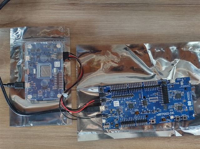
I am using the nRF7002DK development board, which features an nRF5340 as the Host MCU for the nRF7002 chip. I am testing the "Wi-Fi TWT Sample" sample project, which allows me to establish a Target Wake Time (TWT) session between the nRF7002 Wi-Fi module and a Wi-Fi 6 Access Point.

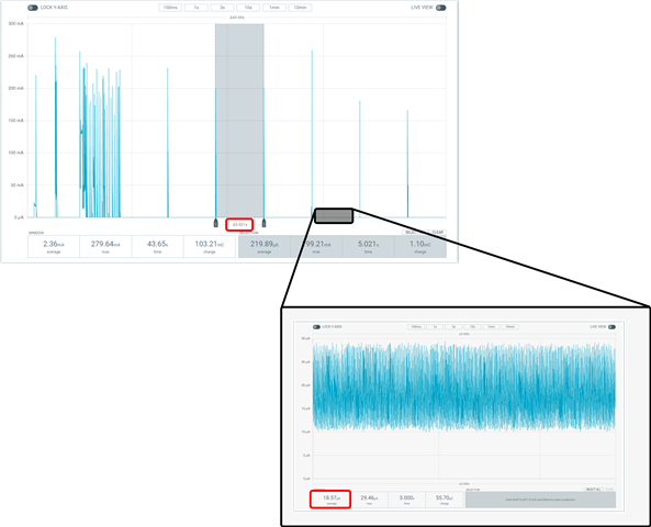
In this particular case, I have configured a TWT interval of 5 seconds. During the time interval between two TWT pings, it is observed that the nRF7002 is in Sleep Mode with a consumption of 18uA, as indicated in its datasheet and the image shown below:

nRF7002 Consumption

However, for my development project, it is a requirement that, between two TWT pings, the nRF5340 Host MCU maintains an average current lower than that presented in the following image (currently at 158uA).

nRF5340 Consumption

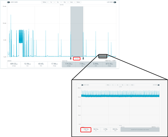
Could you please guide me on any configuration settings for the nRF5340, either in its QSPI interface or its Sleep modes, to reduce the average current consumed by this MCU between TWT intervals?

Parents
  • Hi Holman

    What kind of setup are you using for the measurements? 

    Could you share a diagram or picture showing how the PPK2 is connected? 

    The current draw of the nRF5340 host should be around 18uA in between TWT events, not as high as 158uA. 

    Best regards
    Torbjørn

  • Hi!

    The PPK2 is connected to a nRF7002-DK such that I only can measure the nRF5340 consumption connecting the pin PPK2 VOUT (red wire) to the "->" pin of P22 terminal of the DK, while the PPK2 VIN (brown wire) is connected to the "<-" pin of P22. The PPK2 is configured as "Ampere Meter" to take the measurements. The DK USB terminal is connected to an USB port of my PC, and the same for the USB port of the PPK2. Additionally, the SW6 switch of the DK is set to "DISABLE".

    Finally, the PPK2 GND (black wire) is connected to the "-" terminal of P21.  


    Remark: I am using the nrf7002-DK PCA10143 version.    

    Measurement Setup

    Thank you and best regards.

    Holman.

Reply
  • Hi!

    The PPK2 is connected to a nRF7002-DK such that I only can measure the nRF5340 consumption connecting the pin PPK2 VOUT (red wire) to the "->" pin of P22 terminal of the DK, while the PPK2 VIN (brown wire) is connected to the "<-" pin of P22. The PPK2 is configured as "Ampere Meter" to take the measurements. The DK USB terminal is connected to an USB port of my PC, and the same for the USB port of the PPK2. Additionally, the SW6 switch of the DK is set to "DISABLE".

    Finally, the PPK2 GND (black wire) is connected to the "-" terminal of P21.  


    Remark: I am using the nrf7002-DK PCA10143 version.    

    Measurement Setup

    Thank you and best regards.

    Holman.

Children
Related